
ST 77 Guide
User manual for ST 77
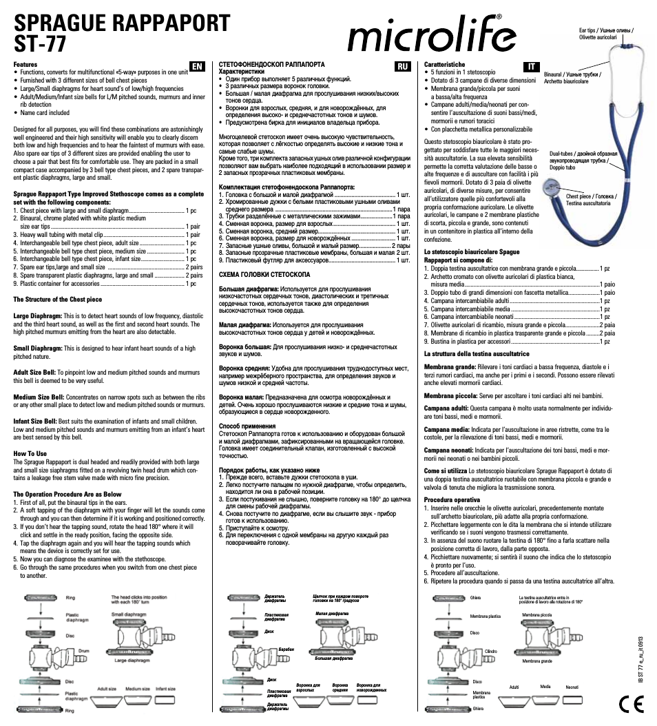
Table of contents
Document Outline
- Contents
- To reduce risk of hazard, do not cover or obstruct the ventilation
- openings. Do not install the Inverter in a zero-clearance compartment.
- Overheating may result.
- wiring is in good electrical condition; and that wire size is not
- undersized.
- Do not operate the Inverter with damaged or substandard Wiring.
- sparks. To prevent fire or explosion do not install in compartments
- containing batteries or flammable materials or in locations which
- require ignition protected equipment. This includes any space
- containing gasoline-powered machinery, fuel tanks, or joints, fittings,
- or other connection between components of the fuel system.
- and water. If acid enters eye, immediately flood eye with running
- cold water for at least 20 minutes and get medical attention
- immediately.
- short-circuit on the battery of other electrical part may cause an
- explosion.
- and watches when working with a lead-acid battery,
- A lead-acid battery produces a short-circuit current high enough to
- weld a ring or the like to metal, causing a severe burn.
- General safety precautions…………………………………………….
- RS - 232C interface / remote controls port
- Power ON/OFF switch, leave in the OFF position during installation.
- 3-1-3. Battery Voltage indicator
- The battery voltage bar graph indicates the voltage at the input terminals of the power inverter. At low input current, this voltage is very close to the battery voltage. At high input current, this voltage will be lower than the battery voltage becau...
- 3-1-4. Battery Voltage indicator
- The AC load watt bar graph indicates the power drawn from the power inverter by the load. For long term operation, the watt indicator should remind in the green & orange area of the bar graph.
- 3-1-5. OVP : Over Voltage indicator
- The over voltage indicator indicates that the power inverter has shut itself down because its input voltage exceeded 12 / 24 VDC version.
- 3-1-6. UVP : Under Voltage Protection indicator
- The under voltage indicator indicates that the power inverter has shut itself down because its input voltage fell below 12 / 24 VDC.
- 3-1-7. OTP : Over Temperature Protection indicator
- The over temp indicator indicates that the power inverter has shut itself down because its temp has become overheated. The power inverter may overheat because it has been operated at power levels above its rating, or because it has been installed i...
- 3-1-8. OLP : Over Load Protection indicator
- The overload indicator indicates that the power inverter has shut itself down because its output has been short circuited or drastically overloaded.
- 3-1-10. AC Outlet (Outlet sockets available):
- Do not obstruct, allow at least 3 inch for air flow.
- Connect to 12V / 24 V battery or the other power sources.
- 【+】is positive, 【-】is negative. Reverse polarity connection will blow internal fuse and may damage inverter permanently.
- 3-2-3. RS-232C
- Connect to remote control unit (option accessory) or taken remote controlled working status by computer.
- 3-2-4. Connect chassis ground terminal to earth or to vehicle chassis using #8 AWG wire.
- 3-4-1. Dry - Do not allow water to drip or splash on the inverter.
- 3-4-2. Cool - Ambient air temperature should be between 0˚C
- 3-4-3. Safe - Do not install in a battery compartment or other areas where flammable fumes may exist, such as fuel storage areas or engine compartments.
- 3-4-4. Ventilated - Allow at least three inch of clearance around the inverter for air flow. Ensure the ventilation openings on the rear and front of the unit are not obstructed.
- 3-4-5. Dust-free - Do not install the Inverter in a dusty environments where are dust, wood particles or other filings/shavings.
- 3-4-6. Close to batteries - Avoid excessive cable lengths but do not install the Inverter in the same compartment as batteries.
- 3-6-1. Neutral Grounding (GFCI’S)
- 3-7-1. Unpack and inspect the power inverter, check to see that the power switch in the OFF position.
- 3-7-2. Connect the cables to the power input terminals on the year panel of power inverter.
- The terminal is positive (+) and black terminal is negative (-).
- Insert the cables into the terminals and tighten allen nut to clamp the wires securely.
- 3-7-3. Before proceeding further, carefully check that cable you have just connected does tie negative terminal of inverter to the negative output power source.
- 3-7-4. Connect the cable from the negative terminal of the inverter to the negative terminal of the power source. Make a secure connection.
- 3-7-5. Set the power switch to the ON position. Check the meters and indicators on the front panel of the inverter. The voltage bar graph should indicate 11 to 14 volts (22 to 28V when 24V version is used) depending on the voltage of the power source....
- The other indicators should be off.
- 3-7-6. Set power inverter switch to the OFF position, the indicator lights may blink and the internal alarm may sound momentarily.
- This is normal. Plug the test load into the AC receptacle on the front panel of the inverter. Leave the test load switch off.
- 3-7-7. Set power inverter switch to the ON position and turn the test load On. The inverter should supply power to the load.
- If you plan to accurately measure the true output r.m.s. voltage of inverter, a meter such as FLUKE 45 BECKMAN 4410 or TRIPLETT 200 must be used.
- 8-1-1. Hardware design:
- This unit uses a 9-pin D connector and three of RS232 signal lines:
- RECEIVE DATA (RXD):PIN2
- TRANSMIT DATA (TXD): PIN3
- DATA TERMINAL READY (DTR):PIN4
- 8-1-2. The connection between this unit and a computer is as follows:
- 8-1-3. The RS232 interface of this unit employs ASCll code to implement the asynchronous serial transmission control.
- The byte structure is START BIP – 8 BIT DATA-STOP BIT Baud rate:1200,2400,4800,(SET BY DIP-SW).
- Parity check :NONE, not settable
- Data bit:8, not settable.
- Stop bit:1, not settable.
- 8-2-1. The Baud Rate of the RS232 interface is determined by S5 and S6 of DIP-SW, as shows in Appendix A.
- Note:You have to reset the unit after adjustment to activate the New settings.
- 8-2-2. Illustration of the RS232 operation:
- 8-2-2-1. RS232 command
- Command format:
- This unit uses high-level language commands with a CR (0DH) and a LF (0AH) as the end of the command.
- The system would interpret and execute the command only after these two characters are received.
- After the unit execute the command, it would send a response string to the computer.
- The response string is as follows:
- = > CR LF:Command executed successfully
- ? > CR LF:Command error, not accepted
- ! > CR LF:Command correct but execution error (e.g. parameters out of range)
- If the command needs any information from the unit, the unit would send the information back to the computer (with CR and LF) and then send the response string to the computer.
- 8-2-2-2. Command format
- This unit supports the following commands.
- There should always be a CR (0DH) and a LF (0AH) appended to the command while sending the command to his unit.
- 8-2-2-3. PWRS command:
- Power saving function control
- Format: PWRS < value>
- Illustration:A space (ASCll code 20H) is needed between PWRS and < value >
- < value > can be one of the following
- “0”:Power saving disable
- “1”:Power saving enable
- “2”:Inquire the status of saving the response information would be either “0” (disable) or “1” (enable)
- 8-2-2-4. Power command
- Power ON/OFF control
- Format:Power < value>
- Illustration:A space (ASCll code 20H) is needed between PWRS and < value >
- < value > can be one of the following
- “0”:Power off, power consumption < 2W, restart time < 5 sec
- “1”:Power off, power consumption <20W, restart time < 2 sec
- “2”:Power on
- “3”:Inquire the status of power on/off status, the response information would be either “0” (OFF) or “1” (OFF) or “2” (ON)
- 8-2-2-5. To query status command
- Format:STUS?
- Illustration:Don’t need to add any of parameter.
- To respond the result be hexadecimal code replaced by 2 ASCll codes that is between 00 ~ FF (0~255), then convert the Hex code to the binary digit after obtaining 8 bytes digit that can be one of following:
- “B0” UVP ( LSB )
- “B1” OVP
- “B2” OLP ( Loading > 110% )
- “B3” FLP ( Loading > 100% / 3min )
- “B4” OTP
- “B5” BATT Too Low
- “B6” BATT Too High
- “B7” BATT Too High ( MSB)
- 8-2-2-6. To query battery level command
- Format:BATT?
- Illustration:Don’t need to add any of parameter.
- To respond the result be Hexadecimal code replaced by 2 ASCll codes and is between 00 ~ 0B, then convert into decade digit after obtaining a digit, between 0 ~ 11, that can be one of following :
- 8-2-2-7. To query load level command:
- Format:Load?
- Illustration:Don’t need adding any of parameter.
- Respond:The same as BATT?
- < value > can be one of following
- SA-1500-112
- SA-1500-124
- Low output voltage
- Load LED bar flash
- And voltage indicator
- in lower red zone
- Over Temp indicator
- on, load less than
- 1500W.
- No output voltage,
- Over Load indicator
- On
- Indication
- Indication
- System Configuration:
- 9-1-1. Plug the 9-pin D-SUB connector of the remote controller in the RS-232 port of the Inverter.
- 9-1-2. Check the setting of DIP-SW S5 & S6, The communication BAUD RATE should be set to 4800bps (S5 & S6 OFF).
- LED Indications:
- 9-1-3. Turn on the switch of the Inverter, There will be two short beep sounds from the Inverter. All LEDS will be ON and, one second later, there will be a short Beep sound. The amber, green and red LEDS of remote controller will be on for 0.5 ...
- The amber LED will be blinking every 2~3 seconds.
- 9-1-3-1. Remote Controller LEDS:
- Green:Power saving enable.1
- Amber:Power saving disable.
- On:Power On
- Blinking:Power Off
- Operations:
- 9-1-4. Set SLIDE SW “ON” (Keypads will not work if SLIDE SW is set “OFF”)
- 9-1-5. Remote ON/OFF:Pressing a button (and releasing in one second) will change (toggle) the output ON/OFF mode and the display of LEDS will be changed accordingly.
- 9-1-6. Operations of power saving mode:
- Press the button for 2 seconds and the colors of LED will be changed.
- Keep pressing the button and the colors will be toggling between amber and green every 2~3 seconds.
- The color of LED will determine the mode of operation.
- Green indicates that power saving mode is enabled and amber indicates is disabled.
- Release the button when the LED indicating the desired status is reached.
- 9-1-7. The operation power saving enable / disable does not change the power ON/OFF mode.
- 9-1-8. Despite the setting of power saving mode, when a power OFF command is set by pressing a button, the power will be turned OFF and the power saving mode will be set to disable automatically (amber LED will flash for 2~3 seconds). When the powe...
- 9-2-1. When an inverter is powered on and is running in idle condition ( there is no load or the load connected to the inverter has been switched off ), it will still draw some power from the batteries for keeping the system alive.
- 9-2-2. This inverter features a power saving “sleep” mode for conserving the battery power during idle conditions. When this mode is enabled, the inverter senses the output power being drawn and if this is less than 2 to 15 watts, the inverter shu...
- 9-2-3. The power saving “sleep” mode can be enabled or disabled with the help of the power on / off switch or with the help of the optional remote control. Procedure to switch between the two states is given at para 6 below. The inverter has bee...
- 9-2-4. Power saving “sleep” mode, enabled
- 9-2-4-1. The front plate has a green led marked “power saving” for indication of enabled state of power saving “sleep” mode (here-in-after referred to as the green led)
- 9-2-4-2. The power saving “sleep” mode is enabled in either of the following indications (When inverter is in on condition):
- The green led flashing sequence is:
- Flash-flash-gap-flash-flash-gap… (power saving “sleep” mode, idle condition or no load) .
- The green led is continuously lighted (power saving “sleep” mode, loaded).
- 9-2-5. Following indications will be observed when the inverter is powered on and subsequently loaded and unloaded when power saving “sleep” mode is in enabled condition: (the initial condition is that the inverter is switched off and all loads are di...
- 9-2-5-1. Switch on the inverter. There will be 2 beeps and the green led will start flashing with a flashing sequence of flash-flash-flash… After about 3 seconds, there will be 1 beep, the green led will stop flashing and it will be lighted continuous...
- The green led will start a flashing sequence of flash-flash-gap-flash-flash-gap… (this indicates that the inverter is in power saving “sleep” mode and is idling at no load).
- 9-2-5-2. If now a load more than 2 to 15 watts is switched on, the green led stops flashing after about 3 seconds and will be lighted continuously. After about 15 to 18 seconds after the green led has stopped flashing and become steady, output power...
- 9-2-5-3. If the load is switched off, the output power will be shut down after about 15 to 18 seconds and the green led will start flashing with a flashing sequence of flash-flash-gap-flash-flash-gap…(this indicates that the inverter is in power savin...
- 9-2-6-1. The front plate has a green led marked “power saving” for indication of enable state of power save “sleep” mode (here-in-after referred to as the green led).
- 9-2-6-2. The power saving “sleep” mode is disabled when the green led marked “power saving” is off. In this mode the output power is always available.
- 9-2-6-3. Following indications will be observed when the inverter is powered on and subsequently loaded and unloaded when power saving “sleep” mode is in disabled condition: (the initial condition is that the inverter is switched off and all loads are...
- 9-2-7. Switching between enabled and disabled states of power saving “sleep” mode
- 9-2-7-1. Switching between enabled and disabled states of power saving “sleep” mode can be done with the help of the power on / off switch on the front plate of the inverter or with the help of the optional remote control.
Related manuals for ST 77


New Manuals
- ZyXEL Communications ZyXEL G-162 Video Gaming Accessories User Manual
- ZyXEL Communications EW103U/A Video Gaming Accessories User Manual
- Western Telematic RSM-8 Video Gaming Accessories User Manual
- Western Telematic RSM-32DC Video Gaming Accessories User Manual
- Western Telematic RSM-32 Video Gaming Accessories User Manual
- Western Telematic RSM-16DC Video Gaming Accessories User Manual
- Western Telematic RSM-16 Video Gaming Accessories User Manual
- Viking Electronics FBI-1A Video Gaming Accessories User Manual
- Viking Electronics DVA-500A Video Gaming Accessories User Manual
- Viking Electronics DVA-3003 Video Gaming Accessories User Manual
- Viking Electronics DVA-2W Video Gaming Accessories User Manual
- Viking Electronics DVA- 1003B Video Gaming Accessories User Manual