
Series 5000 Spring Driven Hose Reels (Low Pressure xxxxELP) Guide
User manual for Series 5000 Spring Driven Hose Reels (Low Pressure xxxxELP)
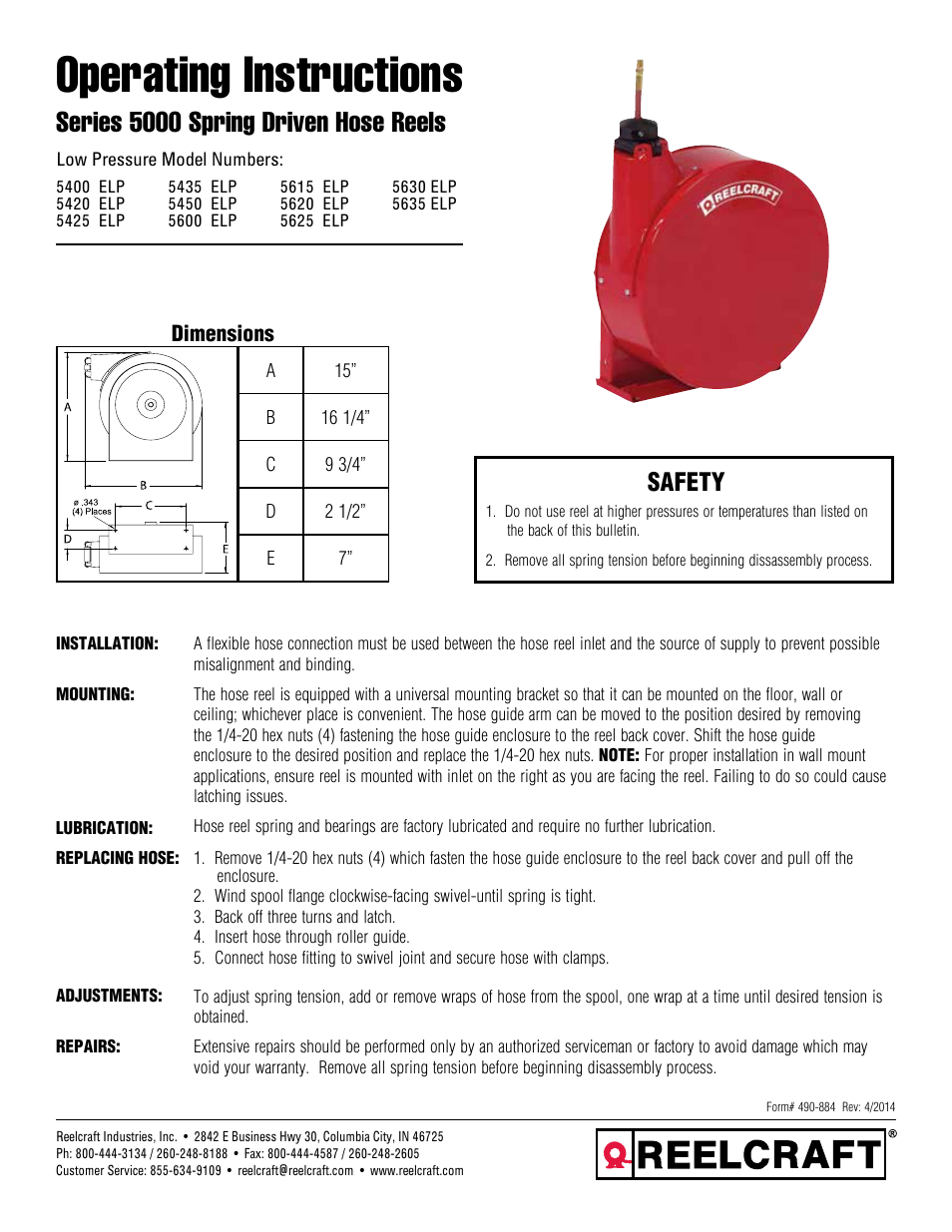

Table of contents
Document Outline
- Safety Messages
- Definitions and Symbols
- Hazardous High Voltage
- General Precautions - Read These First!
- Index to Warnings and Cautions in This Manual
- Cautions and Warnings for Orientation and Mounting Procedures
- Wiring - Warnings for Electrical Practices and Wire Specifications
- Wiring - Cautions for Electrical Practices
- Powerup Test Caution Messages
- Warnings for Configuring Drive Parameters
- Cautions for Configuring Drive Parameters
- Warnings for Operations and Monitoring
- Cautions for Operations and Monitoring
- Warnings and Cautions for Troubleshooting and Maintenance
- General Warnings and Cautions
- UL® Cautions, Warnings, and Instructions
- Table of Contents
- Getting Started
- Inverter Mounting and Installation
- Orientation to Inverter Features
- Basic System Description
- Step-by-Step Basic Installation
- Choosing a Mounting Location
- Ensure Adequate Ventilation
- Keep Debris Out of Inverter Vents
- Check Inverter Dimensions
- Prepare for Wiring
- Determining Wire and Fuse Sizes
- Terminal Dimensions and Torque Specs
- Wire the Inverter Input to a Supply
- Wire the Inverter Output to Motor
- Logic Control Wiring
- Uncover the Inverter Vents
- Powerup Test
- Using the Front Panel Keypad
- Configuring Drive Parameters
- Choosing a Programming Device
- Using Keypad Devices
- “D” Group: Monitoring Functions
- “F” Group: Main Profile Parameters
- “A” Group: Standard Functions
- Control Source Settings
- Basic Parameter Settings
- Analog Input Settings
- Multi-speed and Jog Frequency Setting
- Torque Control Algorithms
- DC Braking Settings
- Frequency-related Functions
- PID Control
- Automatic Voltage Regulation (AVR) Function
- Second Acceleration and Deceleration Functions
- Accel/Decel
- Additional Analog Input Settings
- “B” Group: Fine Tuning Functions
- “C” Group: Intelligent Terminal Functions
- “H” Group: Motor Constants Functions
- “P” Group: Expansion Card Functions
- Operations and Monitoring
- Introduction
- Connecting to PLCs and Other Devices
- Control Logic Signal Specifications
- Intelligent Terminal Listing
- Using Intelligent Input Terminals
- Forward Run/Stop and Reverse Run/Stop Commands:
- Multi-Speed Select
- Jogging Command
- External Signal for DC Braking
- Set Second Motor and Special-Set Second Motor
- Two-stage Acceleration and Deceleration
- Free-run Stop
- External Trip
- Unattended Start Protection
- Software Lock
- Analog Input Current/Voltage Select
- Reset Inverter
- Thermistor Thermal Protection
- Three-wire Interface Operation
- PID ON/OFF and PID Clear
- Remote Control Up and Down Functions
- Force Operation from Digital Operator
- ADD Frequency Enable
- Force Terminal Mode
- Quick Start Enable
- Using Intelligent Output Terminals
- Sinking Outputs, Open Collector
- Sinking Outputs, Open Collector with External Relays
- Internal Relay Output
- Output Signal ON/OFF Delay Function
- Run Signal
- Frequency Arrival Signals
- Overload Advance Notice Signal
- Output Deviation for PID Control
- Alarm Signal
- Analog Input Disconnect Detect
- PID Second Stage Output
- Network Detection Signal
- Logic Output Function
- Option Card Detection Signal
- Analog Input Operation
- Analog Output Operation
- PID Loop Operation
- Configuring the Inverter for Multiple Motors
- Inverter System Accessories
- Troubleshooting and Maintenance
- Glossary and Bibliography
- ModBus Network Communications
- Drive Parameter Settings Tables
- CE-EMC Installation Guidelines
- Index
Related manuals for Series 5000 Spring Driven Hose Reels (Low Pressure xxxxELP)


New Manuals
- ZyXEL Communications ZyXEL G-162 Video Gaming Accessories User Manual
- ZyXEL Communications EW103U/A Video Gaming Accessories User Manual
- Western Telematic RSM-8 Video Gaming Accessories User Manual
- Western Telematic RSM-32DC Video Gaming Accessories User Manual
- Western Telematic RSM-32 Video Gaming Accessories User Manual
- Western Telematic RSM-16DC Video Gaming Accessories User Manual
- Western Telematic RSM-16 Video Gaming Accessories User Manual
- Viking Electronics FBI-1A Video Gaming Accessories User Manual
- Viking Electronics DVA-500A Video Gaming Accessories User Manual
- Viking Electronics DVA-3003 Video Gaming Accessories User Manual
- Viking Electronics DVA-2W Video Gaming Accessories User Manual
- Viking Electronics DVA- 1003B Video Gaming Accessories User Manual