
co614 Guide
User manual for co614
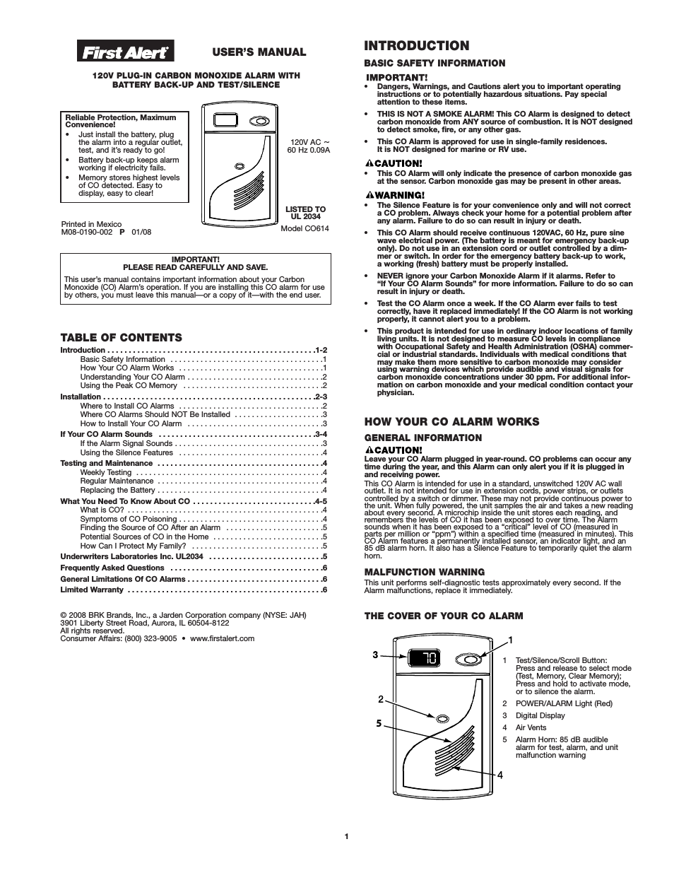

Table of contents
Document Outline
- Back to Main Menu
- Electrical Formulas
- Contents
- SPECIFICATIONS
- PART 1 - GENERAL INFORMATION
- 1.1 Generator Identification
- 1.2 Installation Basics
- 1.3 Non-prepackaged Interconnections
- 1.4 Preparation Before Use
- 1.5 Testing, Cleaning and Drying
- Meters
- The Vom
- Measuring AC Voltage
- Measuring DC Voltage
- Measuring AC Frequency
- Measuring Current
- Measuring Resistance
- Electrical Units
- Ohm’s Law
- Visual Inspection
- Insulation Resistance
- The Megohmmeter
- Stator Insulation Resistance Test (12-20 kW)
- Stator Insulation Resistance Test (8-10 kW)
- Rotor Insulation Resistance Test (8-10 kW)
- Rotor Insulation Resistance Test (12-20 kW)
- Cleaning The Generator
- Drying The Generator
- 1.6 Engine-Generator Protective Devices
- 1.7 Operating Instructions
- 1.8 Automatic Operating Parameters
- PART 2 - AC GENERATORS
- 2.1 Description and Components
- 2.2 Operational Analysis
- 2.3 Troubleshooting Flowcharts
- Problem 1 – Generator Produces ZeroVoltage or Residual Voltage (12-20 kW)
- Problem 2 – Generator Produces ZeroVoltage or Residual Voltage (8/10 kW)
- Problem 3 – Generator ProducesLow Voltage at No-Load
- Problem 4 – Generator ProducesHigh Voltage at No-Load
- Problem 5 – Voltage and Frequency DropExcessively When Loads are Applied
- 2.4 Diagnostic Tests
- Introduction
- Safety
- Test 1 – Check Main Circuit Breaker
- Test 2 – Check AC Output Voltage
- Test 4 – Fixed Excitation Test/RotorAmp Draw Test
- Test 5 – Wire Continuity (12-20 kW)
- Test 6 – Check Field Boost (12-20 kW)
- Test 7 – Testing The Stator With A Vom(12-20 kW)
- Test 8 – Test Brushless Stator
- Test 9 – Check Capacitor
- Test 10 – Test DPE Winding onBrushless units
- Test 11 – Resistance Check Of Rotor Circuit(12-20 kW)
- Test 12 – Check Brushes And Slip Rings(12-20 kW)
- Test 13 – Test Rotor Assembly(12-20 kW)
- Test 14 – Check AC Output Frequency
- Test 15 – Check and Adjust Engine Governor(Single Cylinder Units)
- Test 16 – Check Stepper Motor Control(V-twin Engine Units)
- Test 17 – Check And Adjust VoltageRegulator (12-20 kW)
- Test 18 – Check Voltage And FrequencyUnder Load
- Test 19 – Check For Overload Condition
- Test 20 – Check Engine Condition
- Test 21 – Field Flash Alternator (8-10 kW)
- PART 3 - TRANSFER SWITCH
- 3.1 Description and Components
- 3.2 Operational Analysis
- 3.3 – Troubleshooting Flowcharts
- Introduction To Troubleshooting
- Problem 7 – In Automatic Mode,No Transfer to Standby
- Problem 8 – In Automatic Mode, GeneratorStarts When Loss of Utility Occurs,Generator Shuts Down When UtilityReturns But There Is No Retransfer To UtilityPower / or Generator Transfers to StandbyDuring Exercise Or In Manual Mode
- Problem 9 – Blown F1 or F2 Fuse
- Problem 10 – Units Starts And TransferOccurs When Utility Power Is On
- Problem 11 – No Battery Charge(Pre-Packed Load Center)
- Problem 12 – No Battery Charge(RTSN & RTSE Transfer Switch)
- Problem 13 – No Battery Charge(Gen-Ready Load Center)
- Problem 14 – No Battery Charge(Load Shed Transfer Switch)
- 3.4 Diagnostic Tests
- General
- Test 26 – Check Voltage atTerminal Lugs E1, E2
- Test 27 – Check Manual Transfer SwitchOperation
- Test 28 – Check 23 And 15BWiring/Connections
- Test 29 – Test Transfer Relay TR
- Test 30 – Standby Control Circuit
- Test 31 – Check Wire 23
- Test 32 – Utility Control Circuit
- Test 33 – Test Limit Switch SW2 and SW3
- Test 34 – Check Fuses F1 and F2
- Test 35 – Check N1 and N2 Wiring
- Test 36 – Check N1 and N2 Voltage
- Test 37 – Check Utility Sensing Voltageat the Circuit Board
- Test 38 – Check Utility Sense Voltage
- Test 39 – Check Voltage atTerminal Lugs N1, N2
- Test 40 – Check Battery Charger SupplyVoltage “Pre-Wire Load Center”
- Test 41 – Check Battery Charger OutputVoltage “Pre-Wire Load Center”
- Test 42 – Check Wire 0 and Wire15B“Pre-Wire Load Center”
- Test 43 – Check Battery ChargerSupply Voltage“RTSN & RTSE Transfer Switch”
- Test 44 – Check Battery ChargerOutput Voltage“RTSN & RTSE Transfer Switch"
- Test 45 – Check Wire 0/“RTSN & RTSE Transfer Switch”
- Test 46 – Check Battery ChargerSupply Voltage“GenReady Load Center"
- Test 47 – Check Battery ChargerOutput Voltage“GenReady Load Center"
- Test 48 – Check Wire 0/15B“GenReady Load Center"
- Test 49 – Check Battery ChargerSupply Voltage“Load Shed Transfer Switch"
- Test 50 – Check Battery ChargerOutput Voltage“Load Shed Transfer Switch"
- Test 51 – Check Wire 0 and Wire 15B“Load Shed Transfer Switch"
- PART 4 - DC CONTROL
- 4.1 Description and Components
- 4.2 Operational Analysis
- 4.3 Troubleshooting Flowcharts
- Problem 15 – Engine Will Not CrankWhen Utility Power Source Fails
- Problem 16 – Engine Will Not Crank WhenAUTO-OFF-MANUAL Switchis Set to “MANUAL
- Problem 17 – Engine Cranksbut Won’t Start
- Problem 18 – Engine Starts Hard andRuns Rough / Lacks Power / Backfires
- Problem 19 – Shutdown Alarm /Fault Occurred
- Problem 20 – 7.5 Amp Fuse (F1) Blown
- Problem 21 – Generator Will Not Exercise
- Problem 22 – No Low Speed Exercise
- 4.4 Diagnostic Tests
- Introduction
- Test 56 – Check Position OfAuto-Off- Manual Switch
- Test 57 – Try a Manual Start
- Test 58 – Auto-Off-Manual Switch(V-Twin Only)
- Test 59 – Test Auto Operations
- Test 60 – Check 7.5 Amp Fuse
- Test 61 – Check Battery
- Test 62 – Check Wire 56 Voltage
- Test 63 – Test Starter Contactor Relay(V-twin Only)
- Test 64 – Test Starter Contactor(Single Cylinder Engine)
- Test 65 – Test Starter Motor
- Test 66 – Check Fuel Supply and Pressure
- Test 67 – Check Circuit BoardWire 14 Output
- Test 68 – Check Fuel Solenoid
- Test 69 – Check Choke Solenoid
- Test 70 – Check for Ignition Spark
- Test 71 – Check Spark Plugs
- Test 72 – Check Engine / Cylinder LeakDown Test / Compression Test
- Test 73 – Check Shutdown Wire
- Test 74 – Check and AdjustIgnition Magnetos
- Test 75 – Check Oil Pressure Switchand Wire 86
- Test 76 – Check High OilTemperature Switch
- Test 77 – Check and Adjust Valves
- Test 78 – Check Wire 18 Continuity
- Test 79 – Test Exercise Function
- Test 80 – Check Cranking andRunning Circuits
- Test 81 – Check to see if Low SpeedFunction is enabled
- Test 82 – Check operation of theChoke Solenoid
- PART 5 - OPERATIONAL TESTS
- PART 6 - DISASEMBLY
- PART 7 - ELECTRICAL DATA
- Wiring Diagram, 8 kW Home Standby
- Schematic, 8 kW Home Standby
- Wiring Diagram, 10 kW Home Standby
- Schematic, 10 kW Home Standby
- Wiring Diagram, 14 kW Home Standby
- Schematic, 14 kW Home Standby
- Wiring Diagram, 17 kW Home Standby
- Schematic, 17 kW Home Standby
- Wiring Diagram, 20 kW Home Standby
- Schematic, 20 kW Home Standby
- Wiring Diagram, Home Standby Transfer Switch,9/10/12/16 Circuit
- Schematic, Home Standby Transfer Switch,9/10/12/16 Circuit
Related manuals for co614


New Manuals
- ZyXEL Communications ZyXEL G-162 Video Gaming Accessories User Manual
- ZyXEL Communications EW103U/A Video Gaming Accessories User Manual
- Western Telematic RSM-8 Video Gaming Accessories User Manual
- Western Telematic RSM-32DC Video Gaming Accessories User Manual
- Western Telematic RSM-32 Video Gaming Accessories User Manual
- Western Telematic RSM-16DC Video Gaming Accessories User Manual
- Western Telematic RSM-16 Video Gaming Accessories User Manual
- Viking Electronics FBI-1A Video Gaming Accessories User Manual
- Viking Electronics DVA-500A Video Gaming Accessories User Manual
- Viking Electronics DVA-3003 Video Gaming Accessories User Manual
- Viking Electronics DVA-2W Video Gaming Accessories User Manual
- Viking Electronics DVA- 1003B Video Gaming Accessories User Manual