
6320dpm Guide
User manual for 6320dpm

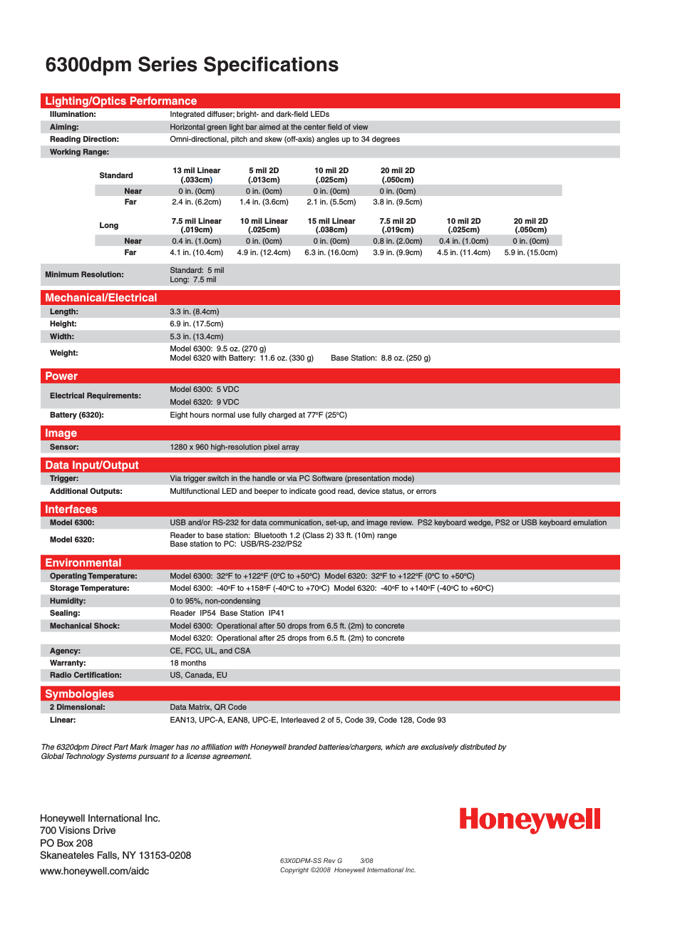
Table of contents
Document Outline
- To the Owner/Operator/Dealer
- DEALER to CUSTOMER Pre-Delivery / Operation Instructions
- TABLE OF CONTENTS
- GENERAL SAFETY INSTRUCTIONS AND PRACTICES
- OPERATOR SAFETY
- CONNECTION OR DISCONNECTING IMPLEMENT SAFETY
- CRUSHING HAZARDS
- THROWN OBJECT HAZARDS
- 1. MARK objects that cannot removed.
- 2. AVOID these objects when mowing.
- 1. BLADES CAN FAIL from impact and objects can be thrown with great velocity.
- 2. INSPECT and REPLACE any damaged blades.
- 3. CHECK blade carrier and REPLACE if damaged.
- RUN OVER HAZARDS
- PTO ENTANGLEMENT HAZARDS
- MOWER BLADE CONTACT HAZARDS
- HIGH PRESSURE OILLEAK HAZARDS
- ELECTRICAL & FIRE HAZARDS
- TRANSPORTING HAZARDS
- HAZARDS WITH MAINTENANCE OF IMPLEMENT
- PARTS INFORMATION
- Decal Location
- 1. D389 1 DANGER Multi-Hazard
- 2. D388 1 DANGER Driveline Hazard
- 3. D137 1 WARNING CCW Blade Rotation
- 4. 00776678 1 DANGER Shear Bolt Length
- 5. 00760657 1 IMPORTANT Genuine Parts
- 6. D302 2 LOGO Rhino (4 x 6)
- 7. 00771283 1 WARRANTY 5 Year
- 8. D303 2 LOGO Rhino (4 x 16)
- 9. 00781322 2 NAME 148
- 10. 2738332 2 REFLECT Red Reflectors
- 11. NFS 1 SER PLT Serial Number Plate
- 12. 00756004 1** DANGER Shield Missing (Not Shown)
- 13. 00756005 1** DANGER Rotating Driveline (Not Shown)
- 14. 03200347 * REFLECT SMV
- 15. 00776031 1 ________ Canister, Operator’s Manual Inside
- 16. 00781398C 1 ________ Operator’s Manual
- 17. 10058000 3 ________ Bolt
- 18. 00024100 3 ________ Flatwasher
- 19. 02959924 3 ________ Locknut
- 20. D454 1 WARNING Crushing Hazard (Decal Under Deck)
- 21. D614 2 WARNING Thrown Object Shield Missing
- 22. D395 1 WARNING Blade Bolt Torque
- 23. D590 1 INSTRUCT Lubrication Chart
- Decal Description
- Federal Laws and Regulations
- SAFETY SECTION
- EQUIPMENT SPECIFICATIONS
- KEY OPERATION POINTS
- RHINO LIMITED WARRANTY
- 1. LIMITED WARRANTIES
- 1.01. Rhino warrants for one year from the purchase date to the original non-commercial, governmental, or municipal purchaser (“Purchaser”) and warrants for six months to the original commercial or industrial purchaser (“Purchaser”) that the ...
- 1.02. Manufacturer will replace for the Purchaser any part or parts found, upon examination at one of its factories, to be defective under normal use and service due to defects in material or workmanship.
- 1.03. This limited warranty does not apply to any part of the goods which has been subjected to improper or abnormal use, negligence, alteration, modification, or accident, damaged due to lack of maintenance or use of wrong fuel, oil, or lubricants, ...
- 1.04. Except as provided herein, no employee, agent, Dealer, or other person is authorized to give any warranties of any nature on behalf of Manufacturer.
- 2. REMEDIES AND PROCEDURES.
- 2.01. This limited warranty is not effective unless the Purchaser returns the Registration and Warranty Form to Manufacturer within 30 days of purchase.
- 2.02. Purchaser claims must be made in writing to the Authorized Dealer (“Dealer”) from whom Purchaser purchased the goods or an approved Authorized Dealer (“Dealer”) within 30 days after Purchaser learns of the facts on which the claim is based
- 2.03. Purchaser is responsible for returning the goods in question to the Dealer.
- 2.04. If after examining the goods and/or parts in question, Manufacturer finds them to be defective under normal use and service due to defects in material or workmanship, Manufacturer will:
- 2.05. Purchaser is responsible for any labor charges exceeding a reasonable amount as determined by Manufacturer and for returning the goods to the Dealer, whether or not the claim is approved. Purchaser is responsible for the transportation cost for...
- 3. LIMITATION OF LIABILITY.
- 3.01. MANUFACTURER DISCLAIMS ANY EXPRESS (EXCEPT AS SET FORTH HEREIN) AND IMPLIED WARRANTIES WITH RESPECT TO THE GOODS INCLUDING, BUT NOT LIMITED TO, MERCHANTABILITY AND FITNESS FOR A PARTICULAR PURPOSE.
- 3.02. MANUFACTURER MAKES NO WARRANTY AS TO THE DESIGN, CAPABILITY, CAPACITY, OR SUITABILITY FOR USE OF THE GOODS.
- 3.03. EXCEPT AS PROVIDED HEREIN, MANUFACTURER SHALL HAVE NO LIABILITY OR RESPONSIBILITY TO PURCHASER OR ANY OTHER PERSON OR ENTITY WITH RESPECT TO ANY LIABILITY, LOSS, OR DAMAGE CAUSED OR ALLEGED TO BE CAUSED DIRECTLY OR INDIRECTLY BY THE GOODS INCLU...
- 3.04. NO ACTION ARISING OUT OF ANY CLAIMED BREACH OF THIS WARRANTY OR TRANSACTIONS UNDER THIS WARRANTY MAY BE BROUGHT MORE THAN TWO (2) YEARS AFTER THE CAUSE OF ACTION HAS OCCURRED.
- 4. MISCELLANEOUS.
- 4.01. Proper Venue for any lawsuits arising from or related to this limited warranty shall be only in Guadalupe County, Texas.
- 4.02. Manufacturer may waive compliance with any of the terms of this limited warranty, but no waiver of any terms shall be deemed to be a waiver of any other term.
- 4.03. If any provision of this limited warranty shall violate any applicable law and is held to be unenforceable, then the invalidity of such provision shall not invalidate any other provisions herein.
- 4.04. Applicable law may provide rights and benefits to purchaser in addition to those provided herein.
- DEALER SETUP INSTRUCTIONS
- SHIELD ASSEMBLY
- SHEAR BOLT DRIVELINE INSTALLATION
- A-FRAME INSTALLATION (Standard Hitch)
- 1. Attach “A” Frames (1) to inside of welded hitch brackets on Mainframe, insert Hitch Pin (12), lockwasher (14) and install nut (13).
- 2. Install the lift straps (3) on outside of top rails on main shield (behind geabox mount) and attach with 1/2” x 1-1/2” bolts (10) and locknuts (9).
- 3. Insert spacer (7) into toggle (11) between “A” Frames (1). Insert 3/4” x 6” bolts (8) through hole in lift straps and spacer (7). Secure with 3/ 4” locknut (9).
- 4. Assemble driveline support flat (15) and retain using 1/2’ x 1-1/2” bolt (10) and locknut (9).
- A-FRAME INSTALLATION (Standard Hitch)
- TAIL WHEEL INSTALLATION (Standard or Quick Hitch)
- 1. Align Tailwheel Beam Weldment (5) between pivot brackets located behind gearbox mount on Mainframe Weldment. NOTE: Long side of caster fork pivot tube is positioned up. Attach the Tailwheel Beam Weldment (5) to the Mainframe Weldment with one 5/8...
- 2. Insert the Caster Fork Weldment (2) into Tailwheel Beam Weldment (5) and retain with Flatwasher (6) and Cotter Pin (7).
- 3. Tighten all bolts to the proper torque. Figure Asm-R-0248
- HYDRAULIC RELIEF ASSEMBLY
- A-FRAME INSTALLATION (Quick Hitch)
- 1. Attach the A-Frame Bars (1) to the right and left Hitch Lugs (8 & 9) with two Hitch Pins (2), washers (4), bushing (4), bushings (32), and Hex nuts (3).
- 2. Attach the Lift Strap Bars (5) to the Mainframe with two 1/2”-13 x 1-3/4” bolts (14), 1/2” flatwasher (15), bushing (27) and 1/2”-13NC locknut (6).
- 3. Attach flex links (7) to A-Frame bars (16) with 3/4” x 5” Hex bolts (12), bushings (30), flatwashers (29), Bushing (31), and Nut (13).
- 4. Insert 1/2” x 2 bolt (10) through flex links (7), rear braces (5) and bushing (28) inserted in rear braces.
- 5. Insert 1/2” x 2 bolt (10) through rear holes in flex link (7) with bushing (28) between and above rear braces. Figure Asm-R-0317
- Front and Rear Deflectors (Standard Equipment)
- OFFSET ADAPTER HITCH (EXTRA EQUIPMENT)
- RHINO 148 ROTARY MOWER
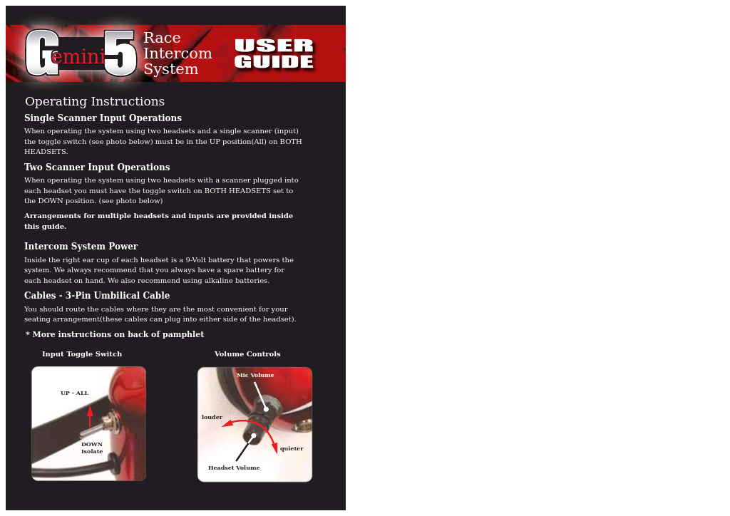
- OPERATION INSTRUCTIONS
- 1. OPERATOR REQUIREMENTS
- 2. TRACTOR REQUIREMENTS
- Tractor Requirements and Capabilities
- 2.1 ROPS and Seat Belt
- 2.2 Tractor Safety Devices
- 2.4 3-Point Hitch
- 2.5 Front End Weight
- 2.6 Power Take Off (PTO)
- 2.7 Tire Spacing
- 3. GETTING ON AND OFF THE TRACTOR
- 4. STARTING THE TRACTOR
- 5. CONNECTING THE MOWER TO THE TRACTOR
- 1. Make sure the tractor is equipped with the correct PTO shaft. Change shafts if needed.
- 2. Shorten or remove the tractor drawbar to avoid interference when raising and lowering the mower.
- 3. Board the tractor and start the engine. Position the tractor to the mower with the 3-point lift arms positioned between the respective set of mower A-frame lift lugs.
- 4. Turn off the tractor engine and dismount.
- 5. One lift arm at a time, align arm end hole between the set of A-frame lift lugs. Insert hitch pin through the lug and arm holes and insert retaining pin into hitch pin.
- 6. Walk around to opposite side and repeat procedure for remaining lift arm and hitch pin.
- 7. Extend or retract 3-point top link to align its end hole with the holes of the mower’s top link. Insert the top link hitch pin and insert retaining pin into hitch pin.
- 8. Adjust any lower link check chains, guide blocks, or sway blocks to prevent the mower from swaying side to side and possible contact with tractor rear tires.
- 5.2 Connecting Mower - Lift Type (Quick Hitch)
- 1. Make certain the implement’s upper and lower hitch pins are secured.
- 2. Lower the tractor’s 3-point lift until the three Quick-Hitch hooks are lower than the implements hitch pins. Carefully back the tractor to align the Quick-Hitch hooks under the implement’s hitch pins.
- 3. Slowly raise the tractor’s 3-point lift until the lower Quick-hitch hooks lock into place over the implement’s 3-point hitch pins.
- 5.3 Safety Tow Chain
- 6. SETTING THE MOWER
- 6.1 Setting Mower Height- Lift Type - (Standard or Quick Hitch)
- 1. Park the tractor and mower on level ground.
- 2. Using the 3-point hitch control lever, position the front of the mower with the side skids 1” less off the ground than desired cut height. For example, for a 3” cut, position the skids 2” from the ground. Set the 3-point control lever stop a...
- 3. Shut down the tractor and remove the key.
- 4. Adjust the mower deck front to rear by extending or retracting the 3-point top link. Always set front of deck 3/4” lower than rear for best performance.
- 5. Level the mower side to side by manipulating one lower lift arm length. On most tractors, at least one of the lift arms is designed to allow for manipulation of its length. Shortening or extending will allow for deck leveling from side to side.
- 6. Securely block up the mower at this height.
- 7. Remove the bolts securing the tailwheel beam positioning bracket to the support brackets and allow the tailwheel to rest at ground level. Align beam and positioning brackets holes with closest set of holes in support brackets and reinstall bolts s...
- 8. Extend the tractor’s top 3-point link so that when lifting the mower, the front of the deck will raise 2 to 2½" before the tail wheel leaves the ground. This will allow the mower to follow the contour of uneven terrain.
- 6.2 Setting Deck Pitch
- 6.1 Setting Mower Height- Lift Type - (Standard or Quick Hitch)
- 7. DRIVELINE ATTACHMENT
- 8. PRE-OPERATION INSPECTION AND SERVICE
- 9. DRIVING THE TRACTOR AND IMPLEMENT
- 10. OPERATING THE TRACTOR AND IMPLEMENT
- 10.1 Foreign Debris Hazards
- 10.2 Bystanders/Passersby Precautions
- 10.3 Engaging the Power Take Off (PTO)
- 10.4 PTO RPM and Ground Speed
- 10.5 Operating the Mower
- 1. MAINTAIN MOWER SHIELDING in good operational condition,
- 2. DAILY INSPECT the condition of the Thrown Object Guards, mower Side Skirts, and skid shoes: Replace or repair worn or damaged guards.
- 3. DAILY INSPECT the condition of the Blades and Blade Bolts. Replace any cracked, worn, bent or damage blades. Always replace blade bolts and nuts when replacing blades. Make sure the blade bolts are properly tightened.
- 4. RAISE CUTTING HEIGHT to 6 INCHES minimum.
- 5. INSPECT AREA thoroughly before mowing to REMOVE potential THROWN OBJECT HAZARDS.
- 6. NEVER ALLOW BLADES to CONTACT SOLID OBJECTS like wire, rocks, posts, curbs, guardrails, or ground while mowing.
- 10.7 Shutting Down the Implement
- 11. DISCONNECTING THE MOWER FROM THE TRACTOR
- 12. MOWER STORAGE
- 13. TRANSPORTING THE TRACTOR AND IMPLEMENT
- 14. TROUBLESHOOTING GUIDE
- Problem Possible Cause Remedy
- Blades worn, dull, or bent. Replace blades.
- (Refer to “Maintenance” section).
- Mower not level side to side. Adjust. (Refer to “Assembly” section)
- Improper height adjustment. Adjust Mower height.
- (Refer to “Assembly” section)
- Low tractor tire pressure on Adjust tire pressure.
- one side. (Refer to your tractor operator's
- manual)
- Turning too fast. Reduce ground speed when turning.
- Tractor tires push grass down. Adjust your tractor wheel spacing.
- (Refer to “Operation” section)
- Damaged Mower pan. Repair or replace as necessary.
- RPM too low Use full PTO speed.
- (Refer to your tractor operator's manual)
- Improper blade for direction of cut. Install blades so rotation is correct.
- rear to hold and circulate material longer. (Refer to Operation Section- Setting the Mower-Setting Deck Height) Reduce ground speed.
- Cutting too high. Lower cutting height. (Refer to Operation Section-Setting the Mower- Setting Deck Pitch)
- Windrowing Material heavy and lush. Raise the front of Mower relative to the or Uneven rear. (Refer to Operation Section-
- Distribution Setting the Mower-Setting Deck
- Height)
- Excessive ground speed Reduce ground speed.
- Conditions too wet. Wait for conditions to dry. Reduce
- ground speed.
- Bolt hole elongated or oversized. Replace Blade Carrier.
- Locknut worn out. Replace Locknut.
- Gearbox Noisy Low Lubricant. Check lubricant level.
- Rough gears. Run in or change Gears.
- Worn Bearing. Replace Bearing.
- Bent Shaft. Replace Oil Seal and Shaft.
- Oil Seal Race rough. Replace Shaft or repair Race.
- Oil Seal installed wrong. Replace Seal.
- Oil Seal not sealing in the housing. Replace Seal or use a sealant on O.D.
- of Seal.
- Oil level too high. Drain oil to proper level.
- Gasket damaged. Replace Gasket.
- Bolts loose. Tighten Bolts.
- Sand hole in casting. Replace castings or gearbox.
- Blades unable to cut that part of ground speed of tractor but keep
- grass pressed down by path of engine running at full PTO wpm.
- tractor tires. Lowering the cutting height may help.
- Dull blades. Sharpen or replace blades.
- Height of cutter lower at rear or See Cutting Height Instructions.
- front.
- Improper type lubricant. Replace with proper lubricant.
- Excessive trash build-up around Remove trash.
- gearbox.
- Bearing or gears set up improperly. Consult your Dealer.
- Excessively 540 RPM.
- Heavy Material. Reduce ground speed. Raise cutting
- height.
- Not using proper pin. Replace only with recommended shear
- pin.
- PTO engaged at high engine RPM Idle engine to engage PTO
- Cutting in rocky conditions Increase cutting height.
- Blade carrier RPM too high. Check gearbox ratios.
- Blades not properly heat treated. Consult your Dealer.
- MAINTENANCE SECTION
- HAZARDS WITH MAINTENANCE OF IMPLEMENT
- PARTS INFORMATION
- Lubrication
- DRIVELINE LUBRICATION
- SHEAR PIN YOKE LUBRICATION
- Problem Possible Cause Remedy
- BLADE SERVICING
- BLADE CARRIER INSPECTION
- BLADE CARRIER INSTALLATION
- SEASONAL CLUTCH MAINTENANCE
- 1. Loosen nuts (Figure Mnt-R-0090) on springs until the springs are free, yet remain secure on bolts.
- 2. Attach cutter to tractor and start the tractor. Set the engine speed at 1200 RPM.
- 3. Mark outer plates as shown in Figure Mnt-R-0090.
- 4. Engage the PTO (approximately one second) and then quickly disengage it. The friction lining plates should break loose (check the mark).
- 5. Turn tractor off. Tighten the nuts on the disc spring clutch until Belleville spring is flat, then loosen each nut 2 turns.
- STORAGE
- 1. Thoroughly clean the cutter.
- 2. Lubricate the cutter as covered in Maintenance Section.
- 3. Tighten all bolts and pins to the recommended torque.
- 4. Check the cutter for worn or damaged parts. Make replacements immediately.
- 5. Place driveline in storage position resting on bracket.
- 6. Store the cutter in a clean, dry place with the cutter housing resting on blocks.
- 7. Use spray touch-up enamel where necessary to prevent rust and maintain the appearance of the cutter.
- PROPER TORQUE FOR FASTENERS
- AEM-FEMA Ind-Agri Mower Manual 10-10.pdf
- English Cover.pdf
- Page 1
- Complete Ind Ag Mower Spanish 10-10.pdf
- Spanish Cover.pdf
- Page 1
- Spanish Cover.pdf
- English Cover.pdf
- Safety Section.pdf
- GENERAL SAFETY INSTRUCTIONS AND PRACTICES
- OPERATOR SAFETY
- CONNECTION OR DISCONNECTING IMPLEMENT SAFETY
- CRUSHING HAZARDS
- THROWN OBJECT HAZARDS
- RUN OVER HAZARDS
- PTO ENTANGLEMENT HAZARDS
- MOWER BLADE CONTACT HAZARDS
- HIGH PRESSURE OILLEAK HAZARDS
- ELECTRICAL & FIRE HAZARDS
- TRANSPORTING HAZARDS
- HAZARDS WITH MAINTENANCE OF IMPLEMENT
- PARTS INFORMATION
- Decal Location
- 4. D389 1 DANGER Multi-Hazard
- 5. D388 1 DANGER Driveline Hazard
- 6. D137 1 WARNING CCW Blade Rotation
- 7. 00776678 1 DANGER Shear Bolt Length
- 8. 00760657 1 IMPORTANT Genuine Parts
- 9. D302 2 LOGO Rhino (4 x 6)
- 10. 00771283 1 WARRANTY 5 Year
- 11. D303 2 LOGO Rhino (4 x 16)
- 12. 00781322 2 NAME 148
- 13. 2738332 2 REFLECT Red Reflectors
- 14. NFS 1 SER PLT Serial Number Plate
- 15. 00756004 1** DANGER Shield Missing (Not Shown)
- 16. 00756005 1** DANGER Rotating Driveline (Not Shown)
- 17. 03200347 * REFLECT SMV
- 18. 00776031 1 ________ Canister, Operator’s Manual Inside
- 19. 00781398C 1 ________ Operator’s Manual
- 20. 10058000 3 ________ Bolt
- 21. 00024100 3 ________ Flatwasher
- 22. 02959924 3 ________ Locknut
- 23. D454 1 WARNING Crushing Hazard (Decal Under Deck)
- 24. D614 2 WARNING Thrown Object Shield Missing
- 25. D395 1 WARNING Blade Bolt Torque
- 26. D590 1 INSTRUCT Lubrication Chart
- Decal Description
- Federal Laws and Regulations
- TABLE OF CONTENTS
Related manuals for 6320dpm


New Manuals
- ZyXEL Communications ZyXEL G-162 Video Gaming Accessories User Manual
- ZyXEL Communications EW103U/A Video Gaming Accessories User Manual
- Western Telematic RSM-8 Video Gaming Accessories User Manual
- Western Telematic RSM-32DC Video Gaming Accessories User Manual
- Western Telematic RSM-32 Video Gaming Accessories User Manual
- Western Telematic RSM-16DC Video Gaming Accessories User Manual
- Western Telematic RSM-16 Video Gaming Accessories User Manual
- Viking Electronics FBI-1A Video Gaming Accessories User Manual
- Viking Electronics DVA-500A Video Gaming Accessories User Manual
- Viking Electronics DVA-3003 Video Gaming Accessories User Manual
- Viking Electronics DVA-2W Video Gaming Accessories User Manual
- Viking Electronics DVA- 1003B Video Gaming Accessories User Manual