
41AY06PR966 Guide
User manual for 41AY06PR966

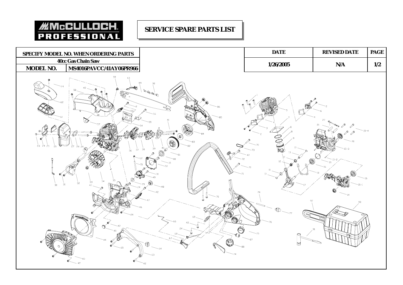
Table of contents
Document Outline
- Preface
- 1.2 The Plug-in Modules
- 1.2.1 Power Supply/Cooling Module
- 1.2.1.1 Multiple Power Supply/Cooling Modules
- 1.2.2 Operators Panel
- 1.2.2.1 Ops Panel Indicators and Switches
- 1.2.3 SCM Input/Output Module
- 1.2.4 Drive Carrier Module
- 1.2.4.1 SATA Dual Path Transition Card
- 1.2.4.2 Drive Status Indicators
- 1.2.4.3 Anti-tamper Locks
- 1.2.5 Dummy Carrier Modules
- 1.2.6 Blank Modules
- 1.3 Visible and Audible Alarms
- 1.4 DCS9550 1S1 Storage Expansion Unit Technical Specification
- 1.4.1 Dimensions
- 1.4.2 Weight
- 1.4.3 AC Power (450W PSU)
- 1.4.4 PSU Safety and EMC Compliance
- 1.4.5 Power Cord
- 1.4.6 Environment
- Table 1-3 Ambient Temperature and Humidity
- 5˚C to 40˚C
- 20% to 80%
- non-condensing
- 23˚C
- 0˚C to +50˚C
- 8% to 80%
- non-condensing
- 27˚C
- 1˚C to +60˚C
- 8% to 80%
- non-condensing
- 29˚C
- -40˚C to +60˚C
- 5% to 100%
- non-precipitating
- 29˚C
- System must be operated with low pressure rear exhaust installation (Back pressure created by rack doors and obstacles not to exceed 5 pascals [0.5mm Water gauge])
- 0 to 2133 m (0 to 7,000ft) (10,000ft at maximum ambient of 35˚C)
- -305 to 12,192m (-1000 to 40,000ft)
- Vertical axis 5g peak 1/2 sine, 10ms
- 30g 10ms 1/2 sine
- 0.21grms 5-500 Hz Random
- 1.04grms 2-200 Hz Random
- 0.3g 2-200 Hz sine
- Table 1-3 Ambient Temperature and Humidity
- 1.4.7 Interfaces
- 1.4.8 SCM I/O Module Specification
- 1.4.9 Drive Carrier Module Specification
- 1.4.10 Software Enclosure Services (SES) Support
- 2
- 2.1 Planning Your Installation
- 2.2 Enclosure Installation Procedures
- 2.3 Power Supply/Cooling Module Installation
- 2.4 SCM I/O Module Configurations
- 2.5 FC-AL Interface
- 2.6 Cabling the IBM System Storage DCS9550 1S1 Storage Expansion Unit
- 2.7 SCM I/O Module Installation
- 2.8 Drive Enclosure Device Addressing
- Table 2-2 Ops Panel Switch Functions (Default settings for DCS9550 1S1 Storage Expansion Unit SCM usage at 1Gb/s)
- Notes 1 ON = switch to the left, OFF = switch to the right.
- Notes 1 Drives are numbered row/column.
- 2 With only one active PSU the enclosure takes approximately 96 seconds to start all drives from Power On.
- 3 * Denotes SES drives which should always be fitted.
- 2.9 Drive Carrier Configuration
- 2.10 Drive Carrier Installation
- 2.11 Power Cord Connection
- 2.12 Grounding Checks
- 3.1 Power On
- 3.2 Ops Panel LEDs
- 3.3 Starting the Drives
- 3.4 Power Down
- 4.1 Emulation Limitations
- 4.2 Initial Start-up Problems
- 4.3 LEDs
- 4.4 Audible Alarm
- 4.5 Troubleshooting
- 4.5.1 System Faults
- 1 The SYSTEM LED will illuminate AMBER on the SCM
- 2 Audible Alarm sound
- 1 Check for other AMBER LED indications on the Power Supply/Cooling modules. If there is a PSU error present there may be a comm...
- 2 Check for other AMBER LED indications on the drive carriers. If none are evident then there may either be an ESI processor problem or a Backplane problem.
- 3 Ops Panel module faulty. Please contact your supplier.
- 4.5.2 Power Supply/Cooling Faults
- 1 Ops Panel FAULT LED AMBER
- 2 An AMBER LED on one or more Power Supply/Cooling Modules.
- 3 Audible Alarm Sounding.
- 1 Any power fault.
- 2 A fan failure.
- 3 A thermal condition which could cause PSU overheating.
- 1 Check Power On/Off Switch on rear of Power Supply/Cooling module is switched ON.(not accessible on later models)
- 2 Check AC Mains Connections to Power Supply/ Cooling module is live.
- 3 Disconnect the Power Supply/Cooling module from mains power and remove the module from the system. Re-install: if problem persists, replace Power Supply/Cooling Module.
- 4 Reduce the ambient temperature.
- 4.5.3 Thermal Control
- 1 Check the installation for any airflow restrictions at either the front or rear of the enclosure. A minimum gap of 25mm at the front and 50mm at the rear is recommended.
- 2 Check for restrictions due to dust build-up; clean as appropriate.
- 3 Check for excessive re-circulation of heated air from rear to the front, use in a fully enclosed rack installation is not recommended.
- 4 Check that all Blank modules are in place.
- 5 Reduce the ambient temperature.
- 4.5.4 Thermal Alarm
- 1 Ops Panel FAULT LED AMBER.
- 2 An AMBER LED on one or more Power Supply/Cooling Modules.
- 3 Audible Alarm Sounding.
- 4 Air temperature exiting PSU above 55˚C.
- 1 Check local ambient environment temperature is below the upper 40˚C specification.
- 2 Check the installation for any airflow restrictions at either the front or rear of the enclosure. A minimum gap of 25mm at the front and 50mm at the rear is recommended.
- 3 Check for restrictions due to dust build-up, clean as appropriate.
- 4 Check for excessive re-circulation of heated air from rear to the front, use in a fully enclosed rack installation is not recommended.
- 5 If possible shutdown the enclosure and investigate the problem before continuing.
- 4.5.5 Thermal Shutdown
- 4.5.1 System Faults
- 4.6 Drive Carrier Module Faults
- 4.7 Dealing with Hardware Faults
- 4.8 Continuous Operation During Replacement
- 4.9 Replacing a Module
- 4.10 Spare Parts and Ancillary Items
- Glossary
- ASCII
- ATA
- (Advance Technology Attachment)
- Attribute
- Backplane
- Bay
- Byte
- Cable
- Character
- Characters Per Second
- Chassis
- Configure
- Data Communications
- Disk (drive, carrier, module)
- Enclosure
- ESI/Ops module
- Hot plugging
- Hot swap
- Hz (Hertz)
- Initialize
- LED
- Module (power supply, drive, I/O)
- Operating system
- Parallel Transmission
- Power Cord
- Protocol
- Redundant
- SCM I/O module (Serial ATA Control I/O module)
- Serial Transmission
- Index
- Glossary
- Notices
- Readers Comments
Related manuals for 41AY06PR966


New Manuals
- ZyXEL Communications ZyXEL G-162 Video Gaming Accessories User Manual
- ZyXEL Communications EW103U/A Video Gaming Accessories User Manual
- Western Telematic RSM-8 Video Gaming Accessories User Manual
- Western Telematic RSM-32DC Video Gaming Accessories User Manual
- Western Telematic RSM-32 Video Gaming Accessories User Manual
- Western Telematic RSM-16DC Video Gaming Accessories User Manual
- Western Telematic RSM-16 Video Gaming Accessories User Manual
- Viking Electronics FBI-1A Video Gaming Accessories User Manual
- Viking Electronics DVA-500A Video Gaming Accessories User Manual
- Viking Electronics DVA-3003 Video Gaming Accessories User Manual
- Viking Electronics DVA-2W Video Gaming Accessories User Manual
- Viking Electronics DVA- 1003B Video Gaming Accessories User Manual