
39MT STARTERS HARDWARE PACKAGES Guide
User manual for 39MT STARTERS HARDWARE PACKAGES
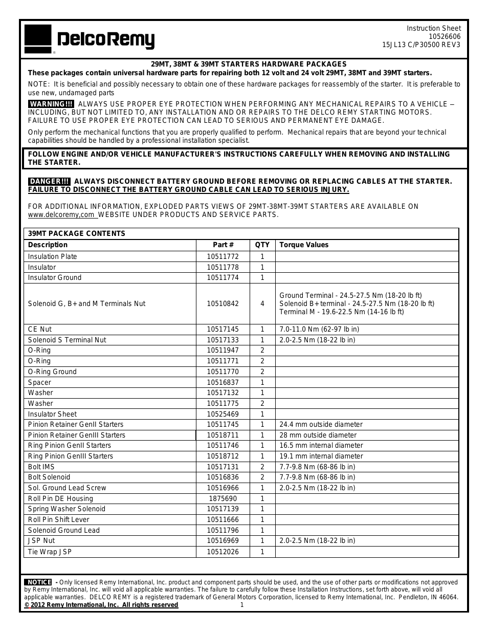


Table of contents Section 3. Chassis & Scissor Arms
Document Outline
- Section A. Introduction - Maintenance Safety Precautions
- Section 1. Specifications
- Section 2. General
- 3.1 Machine Component Covers
- 3.2 Battery Removal/Maintenance
- 3.3 Battery Charger
- 3.4 BATTERY CHARGING
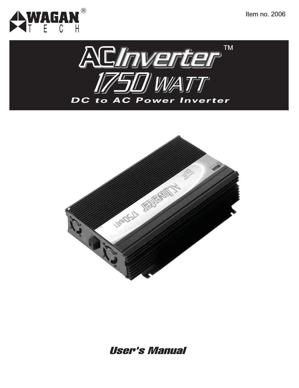
- 3.5 DC to AC Inverter (if equipped)
- 3.6 Ground Control Station
- 3.7 Main Power Contactor Relay
- 3.8 ELEVATION Limit Switch Assembly
- 3.9 LSS - Scissor Arm Angle Sensor - location
- 3.10 Tilt Sensor Replacement
- 3.11 Traction System
- 3.12 Power Control Module - ZAPI
- 3.13 Drive Motor Servicing
- 3.14 Torque Hub Servicing
- 3.15 Steer Assembly Components
- 3.16 Arms and Platform Positioning and Support
- 3.17 Platform Removal
- 3.18 Scissor Arms Removal
- 3.19 Platform Control Station
- Section 4. Hydraulics
- Section 5. JLG Control System
- Section 6. Diagnostic Trouble Codes
- Section 7. General Electrical Information & Schematics
Related manuals for 39MT STARTERS HARDWARE PACKAGES

New Manuals
- ZyXEL Communications ZyXEL G-162 Video Gaming Accessories User Manual
- ZyXEL Communications EW103U/A Video Gaming Accessories User Manual
- Western Telematic RSM-8 Video Gaming Accessories User Manual
- Western Telematic RSM-32DC Video Gaming Accessories User Manual
- Western Telematic RSM-32 Video Gaming Accessories User Manual
- Western Telematic RSM-16DC Video Gaming Accessories User Manual
- Western Telematic RSM-16 Video Gaming Accessories User Manual
- Viking Electronics FBI-1A Video Gaming Accessories User Manual
- Viking Electronics DVA-500A Video Gaming Accessories User Manual
- Viking Electronics DVA-3003 Video Gaming Accessories User Manual
- Viking Electronics DVA-2W Video Gaming Accessories User Manual
- Viking Electronics DVA- 1003B Video Gaming Accessories User Manual