
39MT GEAR REDUCTION HEAVY DUTY STARTING MOTORS Guide
User manual for 39MT GEAR REDUCTION HEAVY DUTY STARTING MOTORS

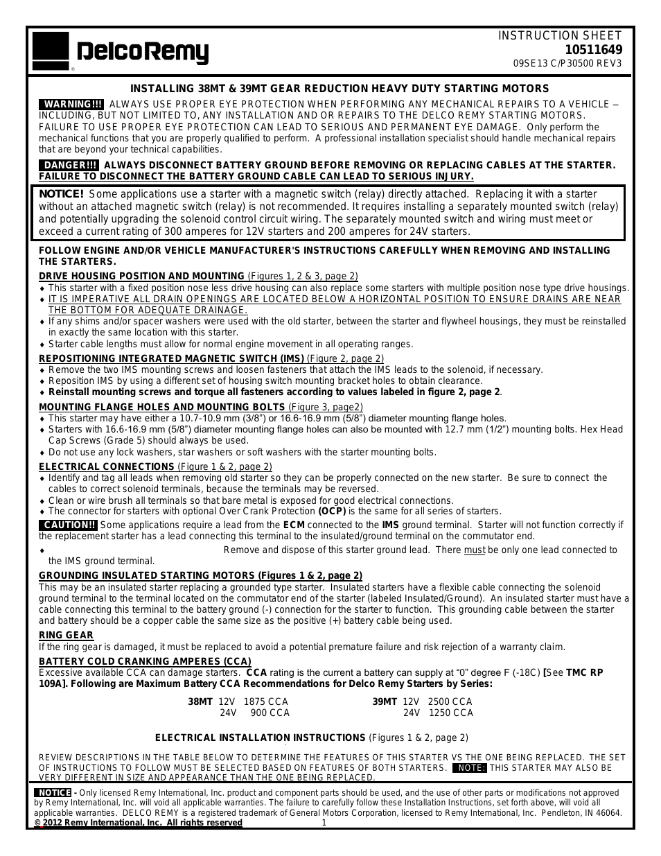
Table of contents
Document Outline
- SECTION 1 FRAME
- FIGURE 1-1. DRIVE AND STEERING INSTALLATION
- FIGURE 1-2. AXLE/BRAKE INSTALLATIONS
- FIGURE 1-3. DRIVE MOTOR ASSEMBLY - 1532E3/1932E3
- FIGURE 1-4. DRIVE MOTOR ASSEMBLY - 2033E3/2046E/32646E3/2658E3
- FIGURE 1-5. JLG POTHOLE PROTECTION SYSTEM INSTALLATION - 1532E3/ 1932E3
- FIGURE 1-6. JLG POTHOLE PROTECTION SYSTEM INSTALLATION - 2033E3/ 2046E3/2646E3/2658E3
- FIGURE 1-7. FRAME MOUNTED COMPONENTS INSTALLATIONS
- FIGURE 1-8. BATTERY CHARGER ASSEMBLY
- SECTION 2 GROUND COMPONENTS
- SECTION 3 SCISSOR ARMS
- FIGURE 3-1. SCISSOR ARMS INSTALLATION - 1532E3
- FIGURE 3-2. SCISSOR ARMS INSTALLATION - 1932E3
- FIGURE 3-3. SCISSOR ARMS INSTALLATION - 2033E3
- FIGURE 3-4. SCISSOR ARMS INSTALLATION - 2046E3
- FIGURE 3-5. SCISSOR ARMS INSTALLATION - 2646E3/2658E3
- FIGURE 3-6. PLATFORM DESCENT DELAY SYSTEM INSTALLATION - 1532E3/ 1932E3/2033E3/2046E3/2646E3
- FIGURE 3-7. ARM GUARDS INSTALLATION - 2658E3
- SECTION 4 PLATFORM
- FIGURE 4-1. PLATFORM INSTALLATION - MANUALLY OPERATED EXTENSION
- FIGURE 4-2. HANDRAILS AND EXTENSION INSTALLATION - STANDARD HANDRAILS (MANUALLY OPERATED) (1532E3/1932E3)
- FIGURE 4-3. HANDRAILS AND EXTENSION INSTALLATION - STANDARD HANDRAILS (MANUALLY OPERATED) (2033E3/2046E3)
- FIGURE 4-4. PLATFORM ACCESS INSTALLATION - STANDARD HANDRAILS (MANUALLY OPERATED) (1532E3/1932E3/2033E3/2046E3)
- FIGURE 4-5. HANDRAILS AND EXTENSION INSTALLATION - FOLDDOWN HANDRAILS (MANUALLY OPERATED) (1532E3/1932E3)
- FIGURE 4-6. HANDRAILS AND EXTENSION INSTALLATION - FOLDDOWN HANDRAILS (MANUALLY OPERATED) (2033E3/2046E3/2646E3/2658E3)
- FIGURE 4-7. PLATFORM ACCESS INSTALLATION - FOLDDOWN HANDRAILS (MANUALLY OPERATED)
- FIGURE 4-8. PLATFORM CONSOLE BOX ASSEMBLY
- FIGURE 4-9. CONTROLLER ASSEMBLY - PQ
- SECTION 5 CYLINDER
- FIGURE 5-1. BRAKE CYLINDER ASSEMBLY
- FIGURE 5-2. LIFT CYLINDER COMPONENTS ASSEMBLY 1532E3/1932E3
- FIGURE 5-3. LIFT CYLINDER COMPONENTS ASSEMBLY 2033E3/2046E3
- FIGURE 5-4. LIFT CYLINDER COMPONENTS ASSEMBLY 2646E3/2658E3
- FIGURE 5-5. STEER CYLINDER ASSEMBLY (PRIOR TO S/N 0200070496)
- FIGURE 5-6. STEER CYLINDER ASSEMBLY (S/N 0200070496 TO S/N 0200078796)
- FIGURE 5-7. STEER CYLINDER ASSEMBLY (S/N 0200078796 TO S/N 0200105071)
- FIGURE 5-8. STEER CYLINDER ASSEMBLY (S/N 0200105071 TO PRESENT)
- SECTION 6 HYDRAULIC
- SECTION 7 ELECTRICAL
- SECTION 8 DECALS
- SECTION 9 RECOMMENDED SERVICE PARTS STOCK
- SECTION 10 SPECIAL OPTIONS
Related manuals for 39MT GEAR REDUCTION HEAVY DUTY STARTING MOTORS


New Manuals
- ZyXEL Communications ZyXEL G-162 Video Gaming Accessories User Manual
- ZyXEL Communications EW103U/A Video Gaming Accessories User Manual
- Western Telematic RSM-8 Video Gaming Accessories User Manual
- Western Telematic RSM-32DC Video Gaming Accessories User Manual
- Western Telematic RSM-32 Video Gaming Accessories User Manual
- Western Telematic RSM-16DC Video Gaming Accessories User Manual
- Western Telematic RSM-16 Video Gaming Accessories User Manual
- Viking Electronics FBI-1A Video Gaming Accessories User Manual
- Viking Electronics DVA-500A Video Gaming Accessories User Manual
- Viking Electronics DVA-3003 Video Gaming Accessories User Manual
- Viking Electronics DVA-2W Video Gaming Accessories User Manual
- Viking Electronics DVA- 1003B Video Gaming Accessories User Manual