
TB303 3 v.2 Guide
User manual for TB303 3 v.2
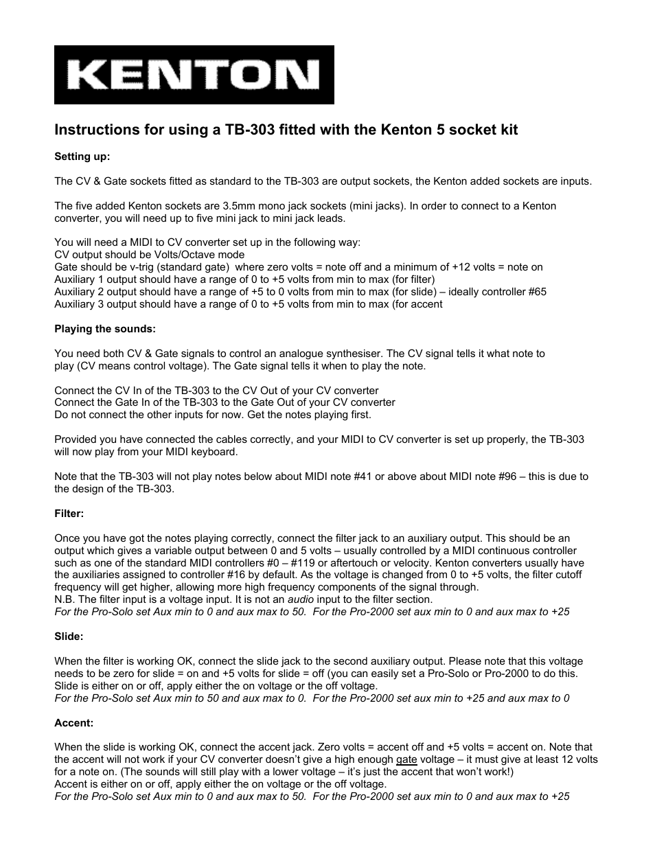

Table of contents
Document Outline
- SECTION 1 - FRAME
- FIGURE 1-1. STEER INSTALLATION
- FIGURE 1-2. TIRE AND WHEEL DRIVE INSTALLATION
- FIGURE 1-3. DRIVE HUB ASSEMBLY (Prior to SN 0300154191)
- FIGURE 1-4. DRIVE HUB ASSEMBLY (E/M400 SN 0300154191 through 0300189901; E/M450 SN 0300154191 through 0300189898)
- FIGURE 1-5. HYDRAULIC COMPONENTS INSTALLATION
- FIGURE 1-6. BRAKE/STEER VALVE ASSEMBLY
- FIGURE 1-7. BATTERIES AND CHARGER INSTALLATION
- FIGURE 1-8. MAC BATTERY CHARGER ASSEMBLY
- FIGURE 1-9. ELECTRICAL COMPONENTS INSTALLATION (FRAMED MOUNTED)
- FIGURE 1-10. YANMAR MOTOR/GENERATOR INSTALLATION (M450 & M400 ONLY)
- FIGURE 1-11. KUBOTA MOTOR/GENERATOR INSTALLATION (M400 & M450 ONLY)
- FIGURE 1-12. FRAME COVERS INSTALLATION
- SECTION 2 - TURNTABLE
- FIGURE 2-1. VALVES AND HORN INSTALLATIONS
- FIGURE 2-2. MAIN CONTROL VALVE ASSEMBLY
- FIGURE 2-3. TURNTABLE AND SWING DRIVE INSTALLATION
- FIGURE 2-4. SWING MOTOR ASSEMBLY (Prior to SN 0300135649)
- FIGURE 2-5. SWING MOTOR ASSEMBLY (E/M400A SN 0300135649 through 0300189901; E/M450A/J SN 0300135649 through 0300189898)
- FIGURE 2-6. SWING BEARING ASSEMBLY
- FIGURE 2-7. FUEL TANK AND MOTOR CONTROL MODULE INSTALLATION (M450 & M400 ONLY)
- FIGURE 2-8. GROUND CONTROL BOX ASSEMBLY
- FIGURE 2-9. HOODS AND BEACON LIGHT INSTALLATIONS
- SECTION 3 - BOOM
- FIGURE 3-1. BOOMS AND CYLINDERS INSTALLATION
- FIGURE 3-2. E/M450A & E/M400A MAIN BOOM ASSEMBLY AND PLATFORM SUPPORT INSTALLATION
- FIGURE 3-3. E/M450AJ MAIN BOOM ASSEMBLY
- FIGURE 3-4. E/M450AJ JIB AND PLATFORM SUPPORT AND ROTATOR INSTALLATION
- FIGURE 3-5. E/M400AJP MAIN BOOM ASSEMBLY
- FIGURE 3-6. E/M400AJP JIB AND PLATFORM SUPPORT AND ROTATOR INSTALLATION
- FIGURE 3-7. ROTATOR ASSEMBLY
- FIGURE 3-8. CABLES/CLAMPS AND LIMIT SWITCHES INSTALLATIONS
- SECTION 4 - PLATFORM
- FIGURE 4-1. PLATFORM COMPONENTS INSTALLATION (FRONT ENTRY PLATFORM)
- FIGURE 4-2. PLATFORM COMPONENTS INSTALLATION (SIDE ENTRY PLATFORM)
- FIGURE 4-3. PLATFORM PADDING INSTALLATION (FRONT ENTRY PLATFORM)
- FIGURE 4-4. PLATFORM PADDING INSTALLATION (SIDE ENTRY PLATFORM)
- FIGURE 4-5. PLATFORM TOP RAIL EXTENSION INSTALLATION (SIDE ENTRY PLATFORM)
- FIGURE 4-6. PLATFORM CONSOLE ASSEMBLY
- FIGURE 4-7. CONTROLLER ASSEMBLY (SWING AND LIFT)
- FIGURE 4-8. CONTROLLER ASSEMBLY (DRIVE AND STEER)
- SECTION 5 - CYLINDER
- FIGURE 5-1. JIB CYLINDER ASSEMBLY (E/M450AJ Prior to SN 0300164333; E/M400AJP Prior to SN 0300163453)
- FIGURE 5-2. JIB CYLINDER ASSEMBLY (E/M450AJ SN 0300164333 through 0300189898; E/M400AJP SN 0300163453 through 0300189901)
- FIGURE 5-3. PLATFORM LEVEL CYLINDER ASSEMBLY (E/M450A Prior to SN 0300165128; E/M400A Prior to SN 0300165128)
- FIGURE 5-4. PLATFORM LEVEL CYLINDER ASSEMBLY (E/M450A SN 0300165128 through 0300189898; E/M400A SN 0300165128 through 0300189901)
- FIGURE 5-5. PLATFORM LEVEL CYLINDER ASSEMBLY - JIB (E/M450AJ Prior to SN 0300163453; E/M400AJP Prior to SN 0300163453)
- FIGURE 5-6. PLATFORM LEVEL CYLINDER ASSEMBLY - JIB (E/M450AJ SN 0300163453 through 0300189898; E/M400AJP SN 0300163453 through 0300189901)
- FIGURE 5-7. LIFT CYLINDER ASSEMBLY - LOWER
- FIGURE 5-8. LIFT CYLINDER ASSEMBLY - MID
- FIGURE 5-9. LIFT CYLINDER ASSEMBLY - UPPER
- FIGURE 5-10. MASTER CYLINDER ASSEMBLY (E/M450A Prior to SN 0300165128; E/M400A Prior to SN 0300165128)
- FIGURE 5-11. MASTER CYLINDER ASSEMBLY (E/M450A SN 0300165128 through 0300189898; E/M400A SN 0300165128 through 0300189901)
- FIGURE 5-12. MASTER CYLINDER ASSEMBLY (E/M450AJ Prior to SN 0300163453; E/M400AJP Prior to SN 0300163453)
- FIGURE 5-13. MASTER CYLINDER ASSEMBLY (E/M450AJ SN 0300163453 through 0300189898; E/M400AJP SN 0300163453 through 0300189901)
- FIGURE 5-14. STEER CYLINDER ASSEMBLY
- FIGURE 5-15. TELESCOPE CYLINDER ASSEMBLY (E/M450A Including 0300175016; E/M450AJ Including 0300175016; E/M400A Prior to SN 0300175016)
- FIGURE 5-16. TELESCOPE CYLINDER ASSEMBLY (E/M450A SN 0300175016 through 0300189898; E/M450AJ SN 0300175016 through 0300189898; E/M400A SN 0300175016 through 0300189901)
- FIGURE 5-17. TELESCOPE CYLINDER ASSEMBLY
- SECTION 6 - HYDRAULIC
- SECTION 7 - ELECTRICAL
- SECTION 8 - DECALS
- SECTION 9 - RECOMMENDED SERVICE PARTS STOCK
- SECTION 10 - SPECIAL OPTIONS
- PART NUMBER INDEX
Related manuals for TB303 3 v.2


New Manuals
- ZyXEL Communications ZyXEL G-162 Video Gaming Accessories User Manual
- ZyXEL Communications EW103U/A Video Gaming Accessories User Manual
- Western Telematic RSM-8 Video Gaming Accessories User Manual
- Western Telematic RSM-32DC Video Gaming Accessories User Manual
- Western Telematic RSM-32 Video Gaming Accessories User Manual
- Western Telematic RSM-16DC Video Gaming Accessories User Manual
- Western Telematic RSM-16 Video Gaming Accessories User Manual
- Viking Electronics FBI-1A Video Gaming Accessories User Manual
- Viking Electronics DVA-500A Video Gaming Accessories User Manual
- Viking Electronics DVA-3003 Video Gaming Accessories User Manual
- Viking Electronics DVA-2W Video Gaming Accessories User Manual
- Viking Electronics DVA- 1003B Video Gaming Accessories User Manual