
SuperNova Thor Guide
User manual for SuperNova Thor
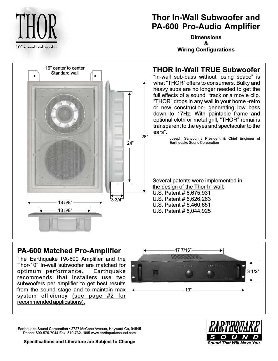
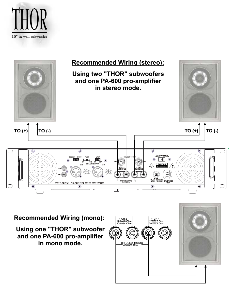
Table of contents
Document Outline
- 1. Characteristics/Specifications
- 2. Typical Connection Diagrams
- 3. Register Quick Reference
- 4. Register Description
- 5. Pin Description - PCM Data mode
- 6. Pin Description - DSD mode
- Table 1. Digital Interface Formats - PCM Modes
- Table 2. Digital Interface Formats - DSD Mode
- Table 3. De-Emphasis Mode Selection
- Table 4. Functional Mode Selection
- Table 5. Soft Cross or Zero Cross Mode Selection
- Table 6. ATAPI Decode
- Table 7. Digital Volume Control
- Table 8. Single Speed (4 to 50 kHz sample rates) Common Clock Frequencies
- Table 9. Double Speed (50 to 100 kHz sample rates) Common Clock Frequencies
- Table 10. Quad Speed (100 to 200 kHz sample rates) Common Clock Frequencies
- Table 11. Single Speed (4 to 50 kHz) Digital Interface Format, Stand-Alone Mode Options
- Table 12. Single Speed Only (4 to 50 kHz) De-Emphasis, Stand-Alone Mode Options
- Table 13. Double Speed (50 to 100 kHz) Digital Interface Format, Stand-Alone Mode Options
- Table 14. Quad Speed (100 to 200 kHz) Digital Interface Format, Stand-Alone Mode Options
- Table 15. Direct Stream Digital (DSD), Stand-Alone Mode Options
- Figure 7. Format 0, Left Justified up to 24-Bit Data
- Figure 8. Format 1, I2S up to 24-Bit Data
- Figure 9. Format 2, Right Justified 16-Bit Data
- Figure 10. Format 3, Right Justified 24-Bit Data
- Figure 11. Format 4, Right Justified 20-Bit Data. (Available in Control Port Mode only)
- Figure 12. Format 5, Right Justified 18-Bit Data. (Available in Control Port Mode only)
- Figure 13. De-Emphasis Curve
- Figure 14. ATAPI Block Diagram
- 7. Applications
- 8. Control Port Interface
- 8.1 SPI Mode
- 8.2 I2C Mode
- Table 16. Memory Address Pointer (MAP)
- Figure 16. Control Port Timing, SPI mode
- Figure 17. Control Port Timing, I2C Mode
- Figure 18. Single-Speed Frequency Response
- Figure 19. Single-Speed Transition Band
- Figure 20. Single-Speed Transition Band
- Figure 21. Single-Speed Stopband Rejection
- Figure 22. Double-Speed Frequency Response
- Figure 23. Double-Speed Transition Band
- Figure 24. Double-Speed Transition Band
- Figure 25. Double-Speed Stopband Rejection
- 9. Parameter Definitions
- 10. References
- 11. Package Dimensions
Related manuals for SuperNova Thor


New Manuals
- ZyXEL Communications ZyXEL G-162 Video Gaming Accessories User Manual
- ZyXEL Communications EW103U/A Video Gaming Accessories User Manual
- Western Telematic RSM-8 Video Gaming Accessories User Manual
- Western Telematic RSM-32DC Video Gaming Accessories User Manual
- Western Telematic RSM-32 Video Gaming Accessories User Manual
- Western Telematic RSM-16DC Video Gaming Accessories User Manual
- Western Telematic RSM-16 Video Gaming Accessories User Manual
- Viking Electronics FBI-1A Video Gaming Accessories User Manual
- Viking Electronics DVA-500A Video Gaming Accessories User Manual
- Viking Electronics DVA-3003 Video Gaming Accessories User Manual
- Viking Electronics DVA-2W Video Gaming Accessories User Manual
- Viking Electronics DVA- 1003B Video Gaming Accessories User Manual