
PJ562 Guide
User manual for PJ562

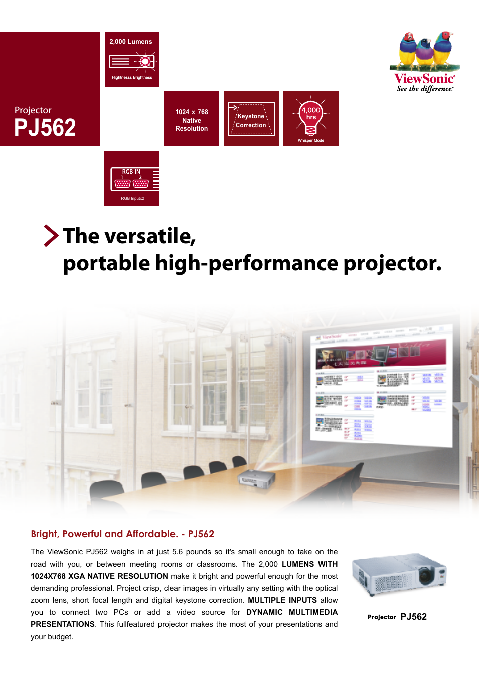
Table of contents
Document Outline
- TNC Models, Software and Features
- New features of the NC software 280 62x-xx and 280 180-xx
- 1 Introduction ..... 1
- 2 Manual Operation, Setup and Probing Functions ..... 15
- 3 Positioning with Manual Data Input (MDI) ..... 37
- 4 Programming: Fundamentals, Files, Program Entry, Spark Erosion, Erosion Tables ..... 41
- 5 Programming: Tools ..... 71
- 6 Programming: Programming Contours ..... 85
- 7 Programming: Miscellaneous functions ..... 119
- 8 Programming: Cycles ..... 129
- 9 Programming: Subprograms and Program Section Repeats ..... 173
- 10 Programming: Q Parameters ..... 185
- 11 Test run and Program Run ..... 215
- 12 MOD Functions ..... 229
- 13 Tables and Overviews ..... 245
- Introduction
- Manual Operation, Setup and Probing Functions
- Positioning with Manual Data Input (MDI)
- Programming: Fundamentals, Files, Program Entry, Spark Erosion, Erosion Tables
- 4.1 Fundamentals of Positioning
- 4.2 Files
- 4.3 Creating and Writing Programs
- 4.4 Automatic Workpiece Change with WP-Call
- 4.5 Fundamentals of Spark Erosion
- 4.6 Erosion Tables
- 4.7 Parameters in the Erosion Table
- To enter erosion parameters in the erosion table
- Power stage (NR)
- Low voltage current (LV)
- High voltage current (HV)
- Gap voltage (GV)
- Pulse-on duration and pulse-off duration
- Servo sensitivity SV
- Erosion time ET, Auto jump distance AJD
- Arc sensitivity (AR)
- Electrode polarity (P)
- High voltage selector HS
- Wear rate WR
- Surface finish RA
- Stock removal SR
- Two-times gap (2G)
- Minimum undersize (UNS)
- Auxiliary parameters AUX 1, AUX 2, ... AUX 6
- Programming: Tools
- Programming: Programming Contours
- Programming: Miscellaneous functions
- Programming: Cycles
- Programming: Subprograms and Program Section Repeats
- Programming: Q Parameters
- 10.1 Principle and Overview
- 10.2 Part Families - Q Parameters in Place of Numerical Values
- 10.3 Describing Contours through Mathematical Operations
- 10.4 Trigonometric Functions
- 10.5 If-Then Decisions with Q Parameters
- 10.6 Checking and Changing Q Parameters
- 10.7 Output of Q Parameters and Messages
- 10.8 Measuring with a probing electrode during program run
- 10.9 Q Parameters with Special Functions
- Test run and Program Run
- 11.1 Graphics
- 11.2 Test run
- 11.3 Program run
- Application
- Background programming
- Operating time
- Changing the erosion parameters during program run
- Running a part program
- Interrupting machining
- Mid-program startup (block scan)
- Resuming program run after an interruption
- Returning to the interruption spot
- Resuming program run with the GOTO key
- Resetting the counters
- Time capture table TIME.W
- MOD Functions
- Tables and Overviews
Related manuals for PJ562


New Manuals
- ZyXEL Communications ZyXEL G-162 Video Gaming Accessories User Manual
- ZyXEL Communications EW103U/A Video Gaming Accessories User Manual
- Western Telematic RSM-8 Video Gaming Accessories User Manual
- Western Telematic RSM-32DC Video Gaming Accessories User Manual
- Western Telematic RSM-32 Video Gaming Accessories User Manual
- Western Telematic RSM-16DC Video Gaming Accessories User Manual
- Western Telematic RSM-16 Video Gaming Accessories User Manual
- Viking Electronics FBI-1A Video Gaming Accessories User Manual
- Viking Electronics DVA-500A Video Gaming Accessories User Manual
- Viking Electronics DVA-3003 Video Gaming Accessories User Manual
- Viking Electronics DVA-2W Video Gaming Accessories User Manual
- Viking Electronics DVA- 1003B Video Gaming Accessories User Manual