
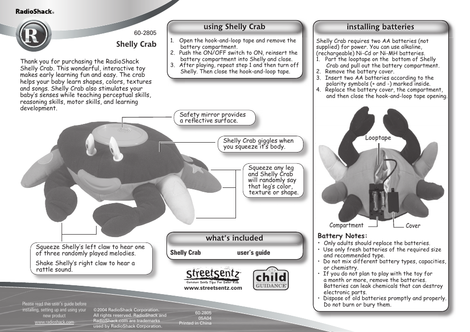
N3570 Guide
User manual for N3570


Table of contents
Document Outline
- Contacting Grass Valley
- Contents
- Section 1 - General 7
- Section 2 - Mounting the Camera 17
- Section 3 - Switch Configuration 23
- Section 4 - System Startup 25
- Appendix A - Troubleshooting 27
- Appendix B - Multi-Camera Applications 29
- Appendix C - Camera Specifications 31
- Appendix D - Pin-Out Diagrams 33
- Appendix E - Field-Of-View Specifications 35
- Appendix F - The 20x Lens Shroud 39
- Appendix G - Typical CameraMan System Diagram 41
- Appendix H - CPT 2018-A3D On-Screen Menus 43
- Appendix I - CPT 2018-A3DP On-Screen Menus 59
- Appendix J - CPT-2018-A3DS On-Screen Menus 77
- Appendix K - CPT-2018-A3DSP On-Screen Menus 93
- Index 101
- Section 1
- Section 2
- Mounting the Camera
- 1. Check the selected camera location to ensure that there is enough camera and cable clearance space (Figure 14) for the CameraMan to pan and tilt without obstruction.
- 2. Locate the zero-degree position mark labeled FRONT on the bottom of the base unit. This mark helps ensure that the base unit ...
- 3. To ensure that the camera-mounting is not prone to vibrations, securely fasten the camera to a rigid flat surface using a 1/4...
- Connecting the Camera System
- Connecting Camera Control Devices
- Camera Control Keypad (or Tracking System Keypad)
- DIGITAL SHOT Director
- Cable Restraint and System Power
- Figure 18. Camera Cable Restraint
- Cable Restraint
- 1. Locate the cable restraint on the back left side of the camera.
- 2. Insert cable(s) through the cable restraint from left to right.
- 3. Tighten the restraint by pulling on the strap’s “free” end to prevent any cable from becoming dislodged. (The cable restraint is reusable and adjustable).
- 4. Group the cables with all the other cables connected to the connector box and follow the instructions below to feed them through the lower cable restraint.
- 1. Insert all cables (upper and lower) through the cable restraint from left to right. This will result in the cables being located approximately in the center of the camera, instead of near the edge.
- 2. Tighten the restraint by pulling on the strap’s “free” end to prevent any cable from becoming dislodged.
- Power Supply Connection
- Mounting the Camera
- Section 3
- Section 4
- System Startup
- 1. Just switch the Power button on the back of the CameraMan DIGITAL Camera to the ON position. The Camera should automatically enter its position calibration mode and then stop at the zero degree point.
- 2. Verify that the camera is now facing in the direction the “FRONT” label was pointing during mounting.
- 3. If you are using the Camera Control Keypad or DIGITAL SHOT Director, make sure its base unit address is the same as on the camera. If they are, verify that the camera’s PAN and TILT functions are working properly.
- System Startup
- Appendix A
- Troubleshooting
- 1. Verify that the SDI OUT connection is being used on the back of the camera shroud.
- 2. Verify that the video output of the camera is connected to the appropriate video input on the switcher or CODEC.
- 1. Verify that the cable being used is wired correctly.
- 2. Verify that the PROTOCOL SELECT switch on the rear configuration panel is set properly.
- 3. Verify that the BASE UNIT ADDRESS on the rear configuration panel is set properly.
- 4. Does the COM light above the RS-232 port on the back of the camera blink when you send a command through this port? If no, change the cable and retry.
- 5. Verify that the POWER LED, on the front of the camera, is illuminated. Also verify that the 12VDC indicator, on the rear of t...
- Troubleshooting
- Appendix B
- Multi-Camera Applications
- 1. Connect cameras together by plugging the Grass Valley T-connector into the RS-485 port on the back of the camera.
- 2. Connect each camera using a 4-conductor cable, with 4-position modular handset plugs wired straight-through:
- 3. Using the BASE UNIT ADDRESS rotary switch located on the back of the Camera, configure each camera with a unique Base Unit Address; i.e. Camera One set with address 0, Camera Two set with address 1, and so on.
- 4. To control each camera with your Camera Control Keypad, the rotary switch inside the keypad battery compartment must match the lowest Base Unit Address in your system.
- Multi-Camera Applications
- Appendix C
- Appendix D
- Appendix E
- 19 x 9 Lens on 16:/4:3 DIGITAL Camera switched to Aspect Ratio without crossover Adaptor.
- Appendix F
- Appendix G
- Appendix H
- CPT 2018-A3D On-Screen Menus
- Use Mode Setting
- Setting by Camera
- 1. Turn the camera on while keeping the MENU switch (Figure 22) depressed.
- 2. The use mode setting menu (Figure 23) appears on the monitor screen and one of the use modes blinks.
- 3. Press the MENU switch, ITEM/AWC switch, or NO/BAR switch to let the desired use mode blink.
- 4. Press the YES/ABC switch. The blinking use mode comes into effect. After the use mode setting menu is shown for about 5 seconds, the camera returns to be ready for operation. Then, the camera operates in the selected use mode.
- CPT 2018-A3D On-Screen Menus
- Menu Item Setting
- Figure 24. Main Menu - Halogen, Fluorescent, Outdoor Mode
- 1. On the camera, keep the MENU switch depressed for 5 seconds or more. The main menu appears on the monitor screen.
- 2. Each time the MENU switch, ITEM/AWC switch, or NO/BAR switch is pressed, the blinking item moves up or down.
- 3. When the YES/ABC switch is pressed after selecting the desired item to blink, the submenu for the selected item appears on the screen.
- 4. Select the desired item to be changed in its settings using the MENU switch and ITEM/AWC switch.
- 5. Press the YES/ABC switch or NO/BAR switch to change the settings.
- 6. Select [Return] using the MENU switch and ITEM/AWC, then press the YES/ABC switch to return to the main menu.
- 7. After changing the settings, take the following steps. Camera alone: Select [End] using the MENU switch and ITEM/AWC switch and press the YES/ABC switch.
- Submenus Overview
- User Mode Submenus Overview
- Initial Settings
- 1. Select [Initialize Data] on the main menu screen of each Use Mode. Press the YES/ABC switch, then the [Initialize Data] screen shows for about 10 seconds.
- 2. Press the YES/ABC switch within about 10 seconds to return to the initial settings, the existing settings are initialized, and the camera returns to main menu
- 3. If the NO/BAR switch is pressed, or if the YES/ABC switch is not pressed, within about 10 seconds, and the camera returns to main menu, then the existing settings are not initialized.
- Resetting
- Initial Settings (User Mode)
- Appendix I
- CPT 2018-A3DP On-Screen Menus
- Use Mode Setting
- Setting by Camera
- 1. Turn the camera on while keeping the MENU switch (Figure 36) depressed.
- 2. The use mode setting menu (Figure 37) appears on the monitor screen and one of the use mode blinks.
- 3. Press the MENU switch, ITEM/AWC switch, or NO/BAR switch to let the desired use mode blink.
- 4. Press the YES/ABC switch. The blinking use mode comes into effect. After the use mode setting menu is shown for about 5 seconds, the camera returns to be ready for operation. Then, the camera operates in the selected use mode.
- CPT 2018-A3DP On-Screen Menus
- Menu Item Setting
- Figure 38. Main Menu - Halogen, Fluorescent, Outdoor Mode
- 1. From the camera alone: Keep the MENU switch depressed for 5 seconds or more. The main menu appears on the monitor screen.
- 2. Each time the MENU switch, ITEM/AWC switch, or NO/BAR switch is pressed, the blinking item moves up or down.
- 3. When the YES/ABC switch is pressed after selecting the desired item to blink, the submenu for the selected item appears on the screen.
- 4. Select the desired item to be changed in its settings using the MENU switch and ITEM/AWC switch.
- 5. Press the YES/ABC switch or NO/BAR switch to change the settings.
- 6. Select [Return] using the MENU switch and ITEM/AWC, then press the YES/ABC switch to return to the main menu.
- 7. After changing the settings, take the following steps. Camera alone: Select [End] using the MENU switch and ITEM/AWC switch and press the YES/ABC switch.
- Submenus Overview
- Initial Settings
- Appendix J
- CPT-2018-A3DS On-Screen Menus
- Use Mode Setting
- Setting by Camera
- 1. Turn the camera on while keeping the MENU switch (Figure 50) depressed
- 2. The use mode setting menu (Figure 51) appears on the monitor screen and one of the use mode blinks
- 3. Press the MENU switch, ITEM/AWC switch, or NO/BAR switch to let the desired use mode blink.
- 4. Press the YES/ABC switch. The blinking use mode comes into effect. After the use mode setting menu is shown for about 5 seconds, the camera returns to be ready for operation. Then, the camera operates in the selected use mode.
- Menu Item Setting
- Figure 52. Main Menu - Halogen, Fluorescent, Outdoor Mode
- 1. Keep the MENU switch depressed for 5 seconds or more. The main menu appears on the monitor screen.
- 2. Each time the MENU switch, ITEM/AWC switch, or NO/BAR switch is pressed, the blinking item moves up or down.
- 3. When the YES/ABC switch is pressed after selecting the desired item to blink, the submenu for the selected item appears on the screen.
- 4. Select the desired item to be changed in its settings using the MENU switch and ITEM/AWC switch.
- 5. Press the YES/ABC switch or NO/BAR switch to change the settings.
- 6. Select [Return] using the MENU switch and ITEM/AWC, then press the YES/ABC switch to return to the main menu.
- 7. After changing the settings, take the following steps. Select [End] using the MENU switch and ITEM/AWC switch and press the YES/ABC switch.
- Changing the Language Setting
- Submenus Overview
- User Mode Submenus Overview
- Initial Settings
- 1. Select [Initialize Data] on the main menu screen of each Use Mode. Press the YES/ABC switch, then the [Initialize Data] screen shows for about 10 seconds.
- 2. Press the YES/ABC switch within about 10 seconds to return to the initial settings, the existing settings are initialized, and the camera returns to main menu
- 3. If the NO/BAR switch is pressed, or if the YES/ABC switch is not pressed, within about 10 seconds, and the camera returns to main menu, then the existing settings are not initialized.
- Resetting
- Initial Settings (User Mode)
- CPT-2018-A3DS On-Screen Menus
- Appendix K
- CPT-2018-A3DSP On-Screen Menus
- Use Mode Setting
- Setting by Camera
- 1. Turn the camera on while keeping the MENU switch () depressed.
- 2. The use mode setting menu (shown below) appears on the monitor screen and one of the use mode blinks
- 3. Press the MENU switch, ITEM/AWC switch, or NO/BAR switch to let the desired use mode blink.
- 4. Press the YES/ABC switch. The blinking use mode comes into effect. After the use mode setting menu is shown for about 5 seconds, the camera returns to be ready for operation. Then, the camera operates in the selected use mode.
- Setting by Camera
- Menu Item Setting
- Figure 66. Main Menu of Halogen, Fluorescent, Outdoor Mode
- 5. Keep the MENU switch depressed for 5 seconds or more. The main menu appears on the monitor screen.
- 6. Each time the MENU switch, ITEM/AWC switch, or NO/BAR switch is pressed, the blinking item moves up or down.
- 7. When the YES/ABC switch is pressed after selecting the desired item to blink, the submenu for the selected item appears on the screen.
- 8. Select the desired item to be changed in its settings using the MENU switch and ITEM/AWC switch.
- 9. Press the YES/ABC switch or NO/BAR switch to change the settings.
- 10. Select [Return] using the MENU switch and ITEM/AWC, then press the YES/ABC switch to return to the main menu.
- 11. After changing the settings, take the following steps. Select [End] using the MENU switch and ITEM/AWC switch and press the YES/ABC switch.
- Changing the Language Setting
- Submenus Overview
- Initial Settings
- Use Mode Setting
- Index
- CPT-2018-A3DSP On-Screen Menus
Related manuals for N3570

New Manuals
- ZyXEL Communications ZyXEL G-162 Video Gaming Accessories User Manual
- ZyXEL Communications EW103U/A Video Gaming Accessories User Manual
- Western Telematic RSM-8 Video Gaming Accessories User Manual
- Western Telematic RSM-32DC Video Gaming Accessories User Manual
- Western Telematic RSM-32 Video Gaming Accessories User Manual
- Western Telematic RSM-16DC Video Gaming Accessories User Manual
- Western Telematic RSM-16 Video Gaming Accessories User Manual
- Viking Electronics FBI-1A Video Gaming Accessories User Manual
- Viking Electronics DVA-500A Video Gaming Accessories User Manual
- Viking Electronics DVA-3003 Video Gaming Accessories User Manual
- Viking Electronics DVA-2W Video Gaming Accessories User Manual
- Viking Electronics DVA- 1003B Video Gaming Accessories User Manual