
MC 202 4 Socket Kit Guide
User manual for MC 202 4 Socket Kit
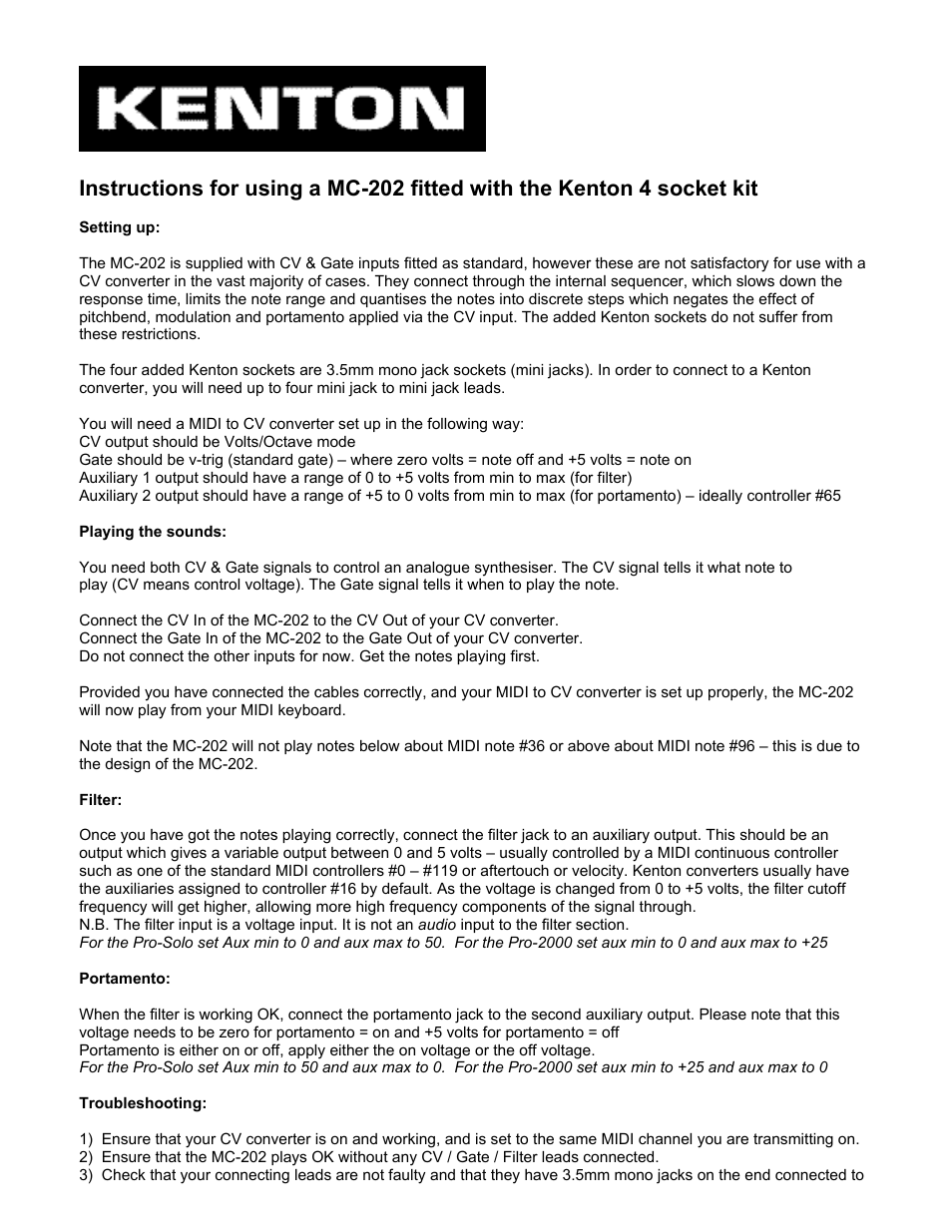

Table of contents
Document Outline
- Maintenance safety precautions
- REVISION LOG
- TABLE OF CONTENTS
- Section 1. MACHINE specifications
- Section 2. GENERAL
- 2.1 MACHINE PREPARATION, INSPECTION, AND MAINTENANCE
- 2.2 Preventive Maintenance and Inspection Schedule
- 2.3 Servicing and Maintenance Guidelines
- General
- Safety and Workmanship
- Cleanliness
- Components Removal and Installation
- Component Disassembly and Reassembly
- Pressure-Fit Parts
- Bearings
- Gaskets
- Bolt Usage and Torque Application
- Hydraulic Lines and Electrical Wiring
- Hydraulic System
- Lubrication and Servicing
- Batteries
- Mast Chain Inspection Procedure
- 2.4 Lubrication Information
- 2.5 Positioning Lift for Access to Components Located Under The Base Frame
- SECTION 3. BASE COMPONENTS
- 3.1 Base Assembly Components
- 3.2 Base Frame Covers
- 3.3 Drive And Caster Wheels
- 3.4 Drive Motor component - servicing
- 3.5 Drive Motor Assembly - Servicing
- Drive Motor Assembly - Removal
- Drive Motor Brake Removal and Adjustment
- Brake Operation (See Figure 3-7.)
- Brake Assembly Removal
- Checking/Adjusting Armature Plate Gap Setting
- Brake Assembly Installation
- Drive Motor Boot Assembly Installation
- Drive Motor Brush Replacement
- Brush Cleaning and Inspection
- Brush Removal
- Brush Reassembly
- Gear Box Disassembly/Assembly
- Gear/Pinion Shaft Assembly
- Drive Shaft Assembly
- Final Gear Box Assembly
- 3.6 Pot Hole Protection System
- 3.7 Battery/Battery Charger - Service Procedures
- Battery Low Voltage Warning Indicators
- Diagnostics
- Battery Condition Testing
- Battery Replacement
- Battery Charger General Information
- Battery Charger Troubleshooting
- Battery Charge/Flash Code LED Indicator on Platform Control Console
- Battery Charging Status Indicators Mounted on Ground Control Station Cover
- Wet/VRLA Battery - Charging Profile Switch
- General Component Installation Notes
- Battery Charger Installation
- Cover Installation
- AC Line Fuse Installation
- Interlock Relay Installation
- Wet/VRLA Switch Installation
- Shunt Assembly Installation
- SCR Rectifier Installation (Either Side)
- Transformer Installation
- Printed Circuit Board Installation
- DC Circuit Breaker/Voltage Select Switch Installation
- SECTION 4. CONTROL COMPONENTS
- 4.1 CONTROL Components Overview
- 4.2 Controls Cover Installation
- 4.3 Control Components - Installation
- 4.4 Ground Control Module - Service Procedure
- 4.5 Ground Control Module - Programming
- 4.6 Platform Control Console - Service Procedures (machines s/n - 0130007616 to present)
- General
- Remove Platform Control Console
- Display/Controller Module Electrical Connections
- Mounting Bracket - Install/Remove
- Rear Cover - Install/Remove
- Display/Controller Module - Install/Remove
- Drive/Lift Mode Switch - Install/Remove
- Horn Button Switch - Install/Remove
- Key Switch - Install/Remove
- E-Stop/ShutDown Switch - Install/Remove
- Joystick Assembly - Install/Remove
- 4.7 Platform Control Console - Service Procedures (machines prior to s/n - 0130007616)
- 4.8 Pump-Motor Assembly - Service Procedure
- 4.9 obstruction sensor system - service procedure (dvsp - option)
- SECTION 5. MAST COMPONENTS
- 5.1 Mast Components Overview
- 5.2 MAST CHAINS AND SEQUENCING CABLES ADJUSTMENT
- 5.3 sequence cable replacement kit
- 5.4 Hydraulic Lift Cylinder - Removal, Inspection and rebuild
- 5.5 Mast Assembly Installation
- 5.6 MAST ASSEMBLY AND DISASSEMBLY PROCEDURES
- 5.7 DVSP - Stockpicker Platform - Installation
- 5.8 DVSP - Stockpicker Platform - Mid-Gate Interlock Installation
- 5.9 mast beacon - Installation
- Section 6. troubleshooting
- 6.1 General
- 6.2 Troubleshooting Information
- 6.3 Hydraulic Circuit Checks
- 6.4 ELECTRICAL CIRCUIT CHECKS
- 6.5 TROUBLESHOOTING TABLES Index
- 6.6 SPECIFICATIONS FOR VARIOUS COMPONENTS
- 6.7 SPECIAL PIN EXTRACTOR TOOLS FOR ELECTRICAL CONNECTORS
- 6.8 FAULT CODE TROUBLESHOOTING TABLES
- Machine in Drive Speed Cut-Back (Turtle) Mode All The Time
- Obstruction Sensor System - Detection
- Battery Voltage Low - Warning Level 3 - Three (3) LED/LCDs lit
- Code 02 - Left PHP Bar - UP
- Code 03 - Right PHP Bar - UP
- Code 04 - Tilt Condition
- Code 05 - Reserved
- Code 06 - Reserved
- Code 07- Left Drive Motor - Disconnected
- Code 08 - Right Drive Motor - Disconnected
- Code 09 - Left Brake - Disconnected
- Code 10 - Right Brake - Disconnected
- Code 11 - Left Drive Motor - Short Circuit
- Code 12 - Right Drive Motor - Short Circuit
- Code 13 - Traction Module - In Fold Back
- Code 14 - Pump Motor - Disconnected
- Code 15 - Lift Down Valve - Disconnected
- Code 16 - Lift Down Valve - Short Circuit
- Code 17 - Ground Control Module - In Fold Back
- Code 18 - Alarm - Short Circuit
- Code 19 - Alarm - Disconnected
- Code 20 - Beacon - Short Circuit
- Code 21 - Beacon - Disconnected
- Code 22 - Horn - Short Circuit
- Code 23 - Horn - Disconnected
- Code 24 - Auxiliary #1 Circuit - Short Circuit
- Code 25 - Auxiliary #1 Circuit - Disconnected
- Code 26 - Auxiliary #2 - Short Circuit
- Code 27 - Auxiliary #2 - Disconnected
- Code 28 - Reserved
- Code 29 - Reserved
- Code 30 - Traction Module - No Communication with Ground Control Module
- Code 31 - Platform Control Console - No Communication with Ground Control Module
- Code 32 - Pump Motor - Over Current
- Code 33 - Both PHP Bars - UP
- Code 38 - Battery Voltage Low - Warning Level 2 - Two (2) LED/LCDs lit
- Code 39 - Battery Voltage Low - Warning Level 3 - One (1) LED/LCDs lit
- Code 40 - Obstruction Sensor System - No Communication with Ground Control Module
- Codes 41 thru 46 - OSS - Sensor 1 through 6 - Fault Condition
- Codes (100 - 199) Ground Control Module - Fault Condition
- Codes (200 - 299) Platform Control Console - Fault Condition
- Codes (300 - 399) Traction Control Module - Fault Condition
- 6.9 MAIN POWER CIRCUIT TROUBLESHOOTING
- 6.10 MAST TROUBLESHOOTING
- 6.11 HYDRAULIC LEAK TROUBLESHOOTING
- 6.12 BASE FRAME COMPONENTS TROUBLESHOOTING
- 6.13 DRIVE SYSTEM TROUBLESHOOTING
Related manuals for MC 202 4 Socket Kit


New Manuals
- ZyXEL Communications ZyXEL G-162 Video Gaming Accessories User Manual
- ZyXEL Communications EW103U/A Video Gaming Accessories User Manual
- Western Telematic RSM-8 Video Gaming Accessories User Manual
- Western Telematic RSM-32DC Video Gaming Accessories User Manual
- Western Telematic RSM-32 Video Gaming Accessories User Manual
- Western Telematic RSM-16DC Video Gaming Accessories User Manual
- Western Telematic RSM-16 Video Gaming Accessories User Manual
- Viking Electronics FBI-1A Video Gaming Accessories User Manual
- Viking Electronics DVA-500A Video Gaming Accessories User Manual
- Viking Electronics DVA-3003 Video Gaming Accessories User Manual
- Viking Electronics DVA-2W Video Gaming Accessories User Manual
- Viking Electronics DVA- 1003B Video Gaming Accessories User Manual