
DC160S-8 6-1 Guide
User manual for DC160S-8 6-1
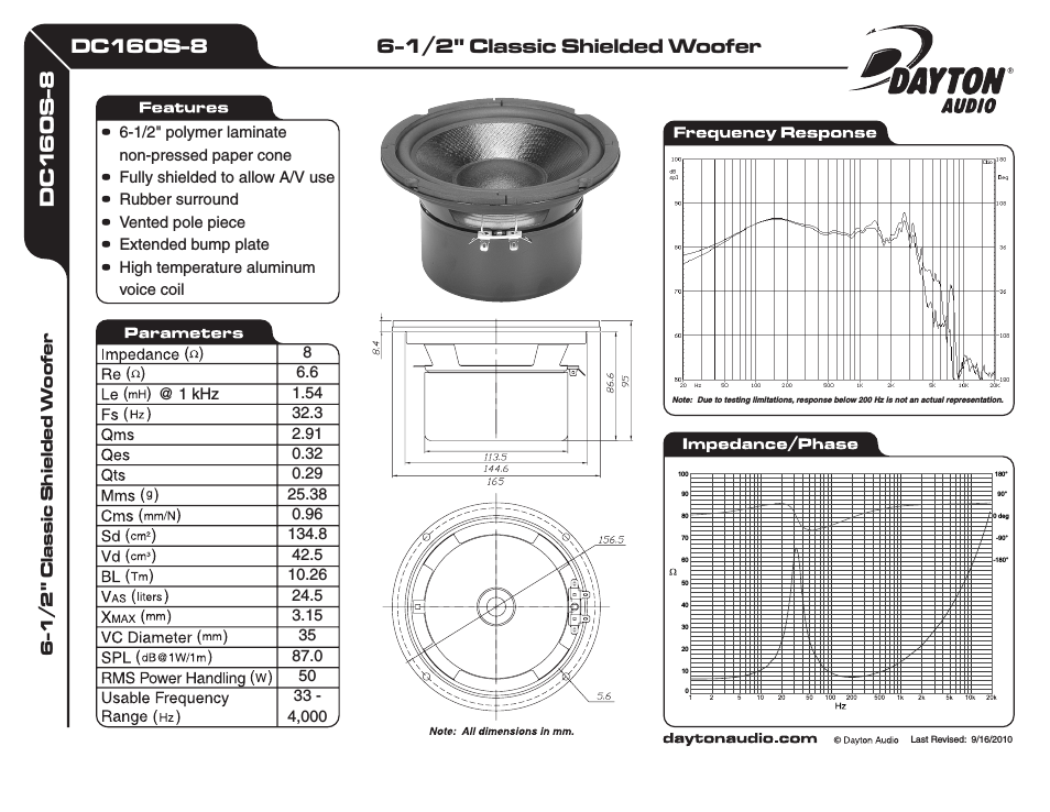
Table of contents
Document Outline
- CONTENTS
- General information
- Safety instructions for electric drives and controllers
- Product description
- General information
- Device description
- Bus connection
- Performance characteristics
- Flexible power management
- Compactness
- Encoder interface
- Input / Output
- Extension and field bus module
- Integrated CANopen interface
- Motion control
- Integrated sequence control
- Integrated safety functions in accordance with EN ISO 13849-1 safety category 3 in the basic unit (see chapter 4)
- Interpolating multi-axis movement
- Parametrisation program "Festo Configuration Tool FCT"
- Interfaces
- Overview of the setpoint value interfaces
- Analogue setpoint specification
- Interfaces for direct synchronous operation
- Output: Generation of increment generator signals [X10]
- Input: Processing of frequency signals [X10]
- Input: Processing of pulse-direction signals 24 V DC [X1]
- Clock frequency of pulse-direction signals
- Activation of synchronization
- Required I/O activation during synchronisation via FCT
- Required I/O triggering during synchronisation via mode switchover with 24 VDC frequency signals
- Required I/O triggering during synchronisation via mode switchover with 5 VDC frequency signals
- I/O Timing Diagram
- General Information
- I/O functions and device control
- RS232 interface (diagnosis/ parametrisation interface)
- Control via RS485
- Multi-firmware strategy
- Motor feedback
- Brake chopper (Brake control)
- Feedback from motor (angle encoder)
- Control interface [X1]
- Increment generator interface [X10]
- SD card holder [M1]
- SD memory card
- Field bus interface
- Function overview
- Operating modes
- Setpoint value processing
- I²t function
- Positioning controller
- Homing
- Trajectory generator
- I/O sequence control
- Safety functions, error messages
- Behaviour when switching off enable
- Oscilloscope function
- Jog and teach function I/O
- Position record linking with positioning/torque control switching
- On-the-fly measurement
- Endless positioning
- Relative positioning records
- Adjustment to the axis and motor construction set
- Functional safety engineering
- General information and intended use
- Integrated function "Safe Torque Off" (STO)
- Integrated function "Safe Stop 1" (SS1)
- General remarks/description "Safe Stop 1" SS1
- Timing diagram, SS1
- Activation of SS1
- Setting the switch-off delay
- Parameterization example FCT
- Sample circuit SS1
- EMERGENCY STOP request, monitoring of protective door
- Restoration of normal operation
- Testing the safety function
- Determination of the brake time
- Setting the delay time
- Mechanical installation
- Electrical installation
- Preparations for commissioning
- Service functions and error messages
- Protective and service functions
- Overview
- Temperatur monitoring for motor and power section, shaft encoder monitoring
- Short-circuit monitoring of the output stage/overload current and short-circuit monitoring
- Voltage monitoring for the intermediate circuit
- I²t monitoring
- Temperature monitoring for the heat sink
- Power monitoring for the brake chopper
- Operating mode and error messages
- Protective and service functions
- Technical data
- Index
Related manuals for DC160S-8 6-1


New Manuals
- ZyXEL Communications ZyXEL G-162 Video Gaming Accessories User Manual
- ZyXEL Communications EW103U/A Video Gaming Accessories User Manual
- Western Telematic RSM-8 Video Gaming Accessories User Manual
- Western Telematic RSM-32DC Video Gaming Accessories User Manual
- Western Telematic RSM-32 Video Gaming Accessories User Manual
- Western Telematic RSM-16DC Video Gaming Accessories User Manual
- Western Telematic RSM-16 Video Gaming Accessories User Manual
- Viking Electronics FBI-1A Video Gaming Accessories User Manual
- Viking Electronics DVA-500A Video Gaming Accessories User Manual
- Viking Electronics DVA-3003 Video Gaming Accessories User Manual
- Viking Electronics DVA-2W Video Gaming Accessories User Manual
- Viking Electronics DVA- 1003B Video Gaming Accessories User Manual