
CSS-C Guide
User manual for CSS-C
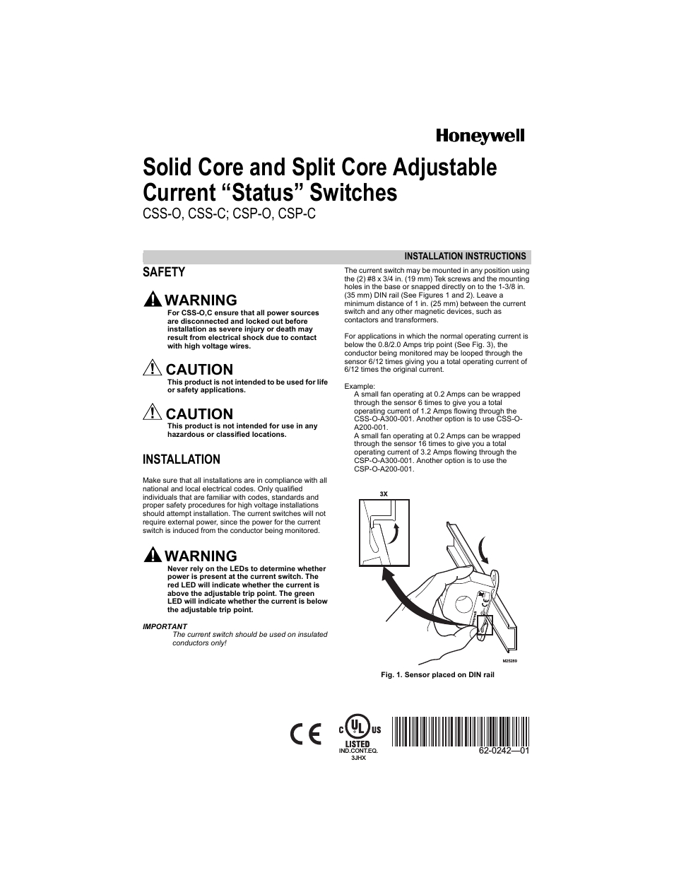


Table of contents About This Manual 1.0 Introduction and System Setup 2.0 Installation 3.0 Adjustments and Calibration 4.0 Service Information
Document Outline
- Contents
- About This Manual 1
- RoughDeck HE AutoLift Option Limited Warranty 15
- © Rice Lake Weighing Systems. All rights reserved. Printed in the United States of America.
- Specifications subject to change without notice.
- Rice Lake Weighing Systems is an ISO 9001 registered company.
- November 17, 2014
- 2.1 Overview
- 2.2 Site Preparation
- 2.3 Unpacking
- 2.4 Electrical Interface to Indicator
- Bare
- #1 (Shield)
- White
- #2 (-Signal)
- Green
- #3 (+Signal)
- Blue
- #4 (-Sense)
- Black
- #5 (-Excitation)
- Yellow
- #6 (+Sense)
- Red
- #7 (+Excitation)
- 4X4
- 63.06
- 49.06
- 49.00
- 63.00
- 41936
- 15.00
- 5X5
- 75.06
- 61.06
- 61.00
- 75.00
- 41397
- 16.75
- 4X6
- 63.06
- 49.06
- 73.00
- 87.00
- 15.00
- Table 2-2: Reference to Figure 2-4 on page 5.
- Figure 2-1. Example Pit Installation Drawing
- 2.6 Cylinder/Platform Installation
- 1. Fit the pivoting intermediate frame over the hinge pins (Figure 2-2, B). The intermediate frame should be seated on the pit coping corner plates (Figure 2-2, C).
- 2. Attach the rod end of each cylinder to the intermediate frame support tube. The cylinder muffler should face upward toward the scale.
- 3. Adjust each cylinder rod until it is approximately 1" from the fully-retracted position (Figure 2-2, D). Place the pivot brackets (Figure 2-2, E) against the pit floor and use them as templates to mark the mounting hole locations. Be sure the air ...
- 4. Drill holes, install anchors, and secure the cylinder pivot brackets to the pit floor.
- 5. Attach the main air line to the inlet side of the regulator (Figure 2-2, F). Attach the air line from the outlet side of the regulator to the input fitting on the pneumatic control box (Figure 2-2, G).
- 6. Attach the air lines from the output fitting on the pneumatic control box to cylinders. Apply 85-100 psi air pressure to the cylinders. Check for air leaks.
- 7. Place the platform scale onto the intermediate frame (Figure 2-2, H), making sure feet sit on corner pads without rocking. Adjust feet as necessary so the platform is level to within 1/4".
- 8. Feed the load cell cables through the conduit. Leave a strain relief loop to allow enough cable for free movement of the scale in the lifted position without tension in the cables (Figure 2-2, J).
- 9. Route the load cell cables through the fittings in the junction box (Figure 2-2, K). Wire the cables to the junction box according to the corner numbering diagram (Figure ) and load cell wiring chart (Table 2-3). Coil and store excess cable before...
- 10. Adjust speed during the lift cycle using the up speed adjustment screw (Figure 2-2, L) in the pneumatic control box. Once you have achieved the desired speed, tighten the lock nut. Adjust descent speed using the down speed adjustment screw (Figur...
- Red
- +Excitation
- Black
- -Excitation
- Green
- +Signal
- White
- -Signal
- Base or Clear
- Shield
Related manuals for CSS-C
New Manuals
- ZyXEL Communications ZyXEL G-162 Video Gaming Accessories User Manual
- ZyXEL Communications EW103U/A Video Gaming Accessories User Manual
- Western Telematic RSM-8 Video Gaming Accessories User Manual
- Western Telematic RSM-32DC Video Gaming Accessories User Manual
- Western Telematic RSM-32 Video Gaming Accessories User Manual
- Western Telematic RSM-16DC Video Gaming Accessories User Manual
- Western Telematic RSM-16 Video Gaming Accessories User Manual
- Viking Electronics FBI-1A Video Gaming Accessories User Manual
- Viking Electronics DVA-500A Video Gaming Accessories User Manual
- Viking Electronics DVA-3003 Video Gaming Accessories User Manual
- Viking Electronics DVA-2W Video Gaming Accessories User Manual
- Viking Electronics DVA- 1003B Video Gaming Accessories User Manual