
BRILLIANTCOLOR PJD6241 Guide
User manual for BRILLIANTCOLOR PJD6241
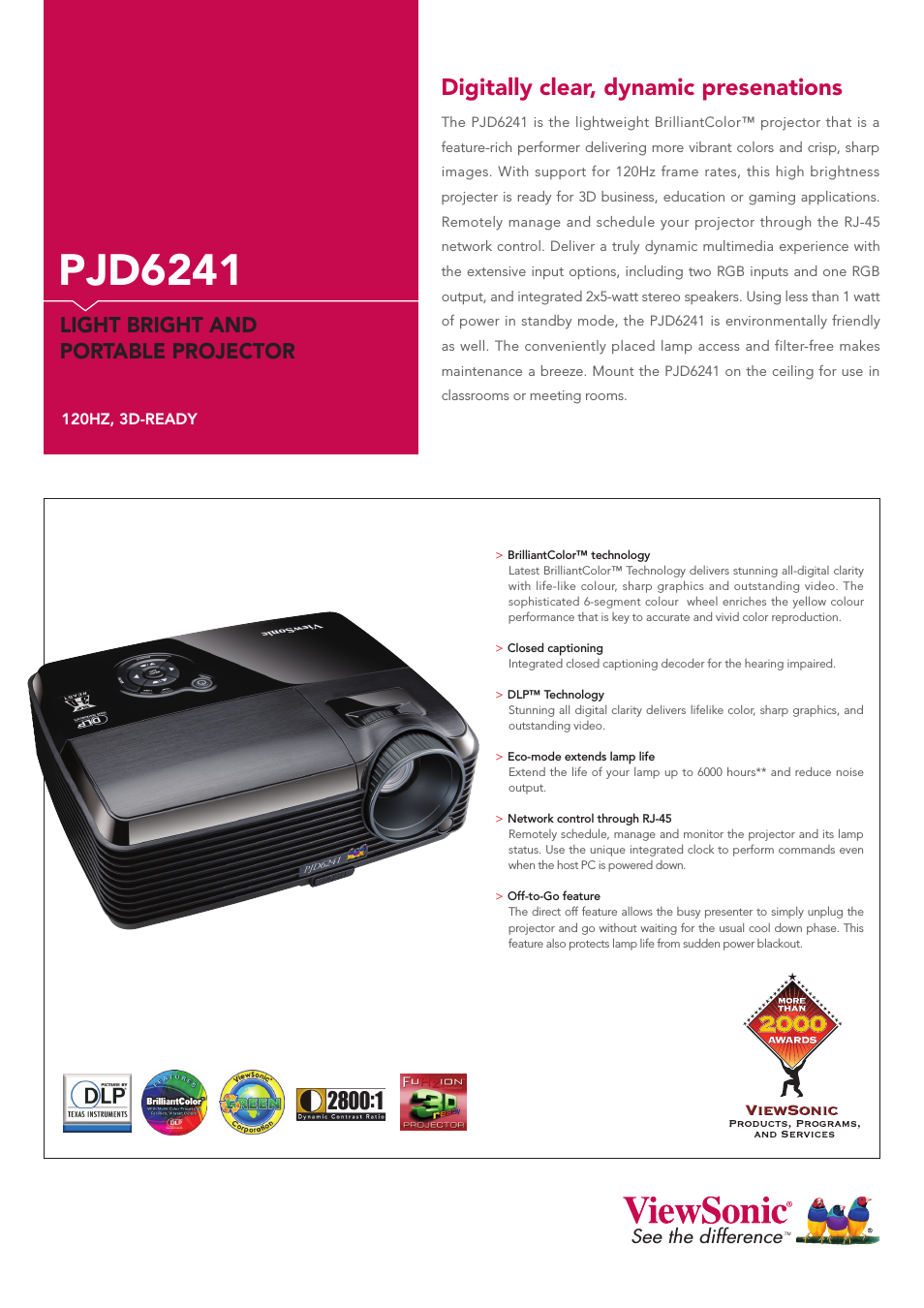

Table of contents
Document Outline
- About this Manual
- TNC Model, Software and Features
- New Cycle Functions of Software 340 49x-02
- New Cycle Functions of Software 340 49x-03
- New Cycle Functions of Software 340 49x-04
- New Cycle Functions of Software 340 49x-05
- New Cycle Functions of Software 340 49x-06 and 606 42x-01
- New Cycle Functions of Software 340 49x-07 and 606 42x-02
- Cycle Functions Changed Since the Predecessor Versions 340 422-xx and 340 423-xx
- Changed Cycle Functions of Software 340 49x-05
- Changed Cycle Functions of Software 340 49x-06 and 606 42x-01
- Changed Cycle Functions of Software 340 49x-07 and 606 42x-02
- Fundamentals / Overviews
- Using Fixed Cycles
- 2.1 Working with Fixed Cycles
- 2.2 Program Defaults for Cycles
- Overview
- Entering GLOBAL DEF
- Using GLOBAL DEF information
- Global data valid everywhere
- Global data for drilling operations
- Global data for milling operations with pocket cycles 25x
- Global data for milling operations with contour cycles
- Global data for positioning behavior
- Global data for probing functions
- 2.3 Pattern Definition PATTERN DEF
- 2.4 Point Tables
- Fixed Cycles: Drilling
- 3.1 Fundamentals
- 3.2 CENTERING (Cycle 240, DIN/ISO: G240)
- 3.3 DRILLING (Cycle 200)
- 3.4 REAMING (Cycle 201, DIN/ISO: G201)
- 3.5 BORING (Cycle 202, DIN/ISO: G202)
- 3.6 UNIVERSAL DRILLING (Cycle 203, DIN/ISO: G203)
- 3.7 BACK BORING (Cycle 204, DIN/ISO: G204)
- 3.8 UNIVERSAL PECKING (Cycle 205, DIN/ISO: G205)
- 3.9 BORE MILLING (Cycle 208)
- 3.10 SINGLE-FLUTED DEEP-HOLE DRILLING (Cycle 241, DIN/ISO: G241)
- 3.11 Programming Examples
- Fixed Cycles: Tapping / Thread Milling
- 4.1 Fundamentals
- 4.2 TAPPING NEW with a Floating Tap Holder (Cycle 206, DIN/ISO: G206)
- 4.3 RIGID TAPPING without a Floating Tap Holder NEW (Cycle 207, DIN/ISO: G207)
- 4.4 TAPPING WITH CHIP BREAKING (Cycle 209, DIN/ISO: G209)
- 4.5 Fundamentals of Thread Milling
- 4.6 THREAD MILLING (Cycle 262, DIN/ISO: G262)
- 4.7 THREAD MILLING/ COUNTERSINKING (Cycle 263, DIN/ISO: G263)
- 4.8 THREAD DRILLING/MILLING (Cycle 264, DIN/ISO: G264)
- 4.9 HELICAL THREAD DRILLING/MILLING (Cycle 265, DIN/ISO: G265)
- 4.10 OUTSIDE THREAD MILLING (Cycle 267, DIN/ISO: G267)
- 4.11 Programming Examples
- Fixed Cycles: Pocket Milling / Stud Milling / Slot Milling
- 5.1 Fundamentals
- 5.2 RECTANGULAR POCKET (Cycle 251, DIN/ISO: G251)
- 5.3 CIRCULAR POCKET (Cycle 252, DIN/ISO: G252)
- 5.4 SLOT MILLING (Cycle 253, DIN/ISO: G253)
- 5.5 CIRCULAR SLOT (Cycle 254, DIN/ISO: G254)
- 5.6 RECTANGULAR STUD (Cycle 256, DIN/ISO: G256)
- 5.7 CIRCULAR STUD (Cycle 257, DIN/ISO: G257)
- 5.8 Programming Examples
- Fixed Cycles: Pattern Definitions
- Fixed Cycles: Contour Pocket, Contour Trains
- 7.1 SL Cycles
- 7.2 CONTOUR GEOMETRY (Cycle 14, DIN/ISO: G37)
- 7.3 Overlapping Contours
- 7.4 CONTOUR DATA (Cycle 20, DIN/ISO: G120)
- 7.5 PILOT DRILLING (Cycle 21, DIN/ISO: G121)
- 7.6 ROUGH-OUT (Cycle 22, DIN/ISO: G122)
- 7.7 FLOOR FINISHING (Cycle 23, DIN/ISO: G123)
- 7.8 SIDE FINISHING (Cycle 24, DIN/ISO: G124)
- 7.9 CONTOUR TRAIN DATA (Cycle 270, DIN/ISO: G270)
- 7.10 CONTOUR TRAIN (Cycle 25, DIN/ISO: G125)
- 7.11 TROCHOIDAL SLOT (Cycle 275, DIN/ISO: G275)
- 7.12 THREE-D CONTOUR TRAIN (Cycle 276, DIN/ISO: G276)
- 7.13 Programming Examples
- Fixed Cycles: Cylindrical Surface
- 8.1 Fundamentals
- 8.2 CYLINDER SURFACE (Cycle 27, DIN/ISO: G127, Software Option 1)
- 8.3 CYLINDER SURFACE Slot Milling (Cycle 28, DIN/ISO: G128, Software Option 1)
- 8.4 CYLINDER SURFACE Ridge Milling (Cycle 29, DIN/ISO: G129, Software Option 1)
- 8.5 CYLINDER SURFACE Outside Contour Milling (Cycle 39, DIN/ISO: G139, Software Option 1)
- 8.6 Programming Examples
- Fixed Cycles: Contour Pocket with Contour Formula
- Fixed Cycles: Multipass Milling
- Cycles: Coordinate Transformations
- 11.1 Fundamentals
- 11.2 DATUM SHIFT (Cycle 7, DIN/ISO: G54)
- 11.3 DATUM SHIFT with datum tables (Cycle 7, DIN/ISO: G53)
- Effect
- Please note while programming:
- Cycle parameters
- Selecting a datum table in the part program
- Editing the datum table in the Programming and Editing mode of operation
- Editing a datum table in a Program Run operating mode
- Transferring the actual values into the datum table
- Configuring the datum table
- Exiting a datum table
- 11.4 DATUM SETTING (Cycle 247, DIN/ISO: G247)
- 11.5 MIRROR IMAGE (Cycle 8, DIN/ISO: G28)
- 11.6 ROTATION (Cycle 10, DIN/ISO: G73)
- 11.7 SCALING (Cycle 11, DIN/ISO: G72)
- 11.8 AXIS-SPECIFIC SCALING (Cycle 26)
- 11.9 WORKING PLANE (Cycle 19, DIN/ISO: G80, Software Option 1)
- Effect
- Please note while programming:
- Cycle parameters
- Resetting
- Positioning the axes of rotation
- Position display in the tilted system
- Workspace monitoring
- Positioning in a tilted coordinate system
- Combining coordinate transformation cycles
- Automatic workpiece measurement in the tilted system
- Procedure for working with Cycle 19 WORKING PLANE
- 11.10 Programming Examples
- Cycles: Special Functions
- 12.1 Fundamentals
- 12.2 DWELL TIME (Cycle 9, DIN/ISO: G04)
- 12.3 PROGRAM CALL (Cycle 12, DIN/ISO: G39)
- 12.4 ORIENTED SPINDLE STOP (Cycle 13, DIN/ISO: G36)
- 12.5 TOLERANCE (Cycle 32, DIN/ISO: G62)
- 12.6 ENGRAVING (Cycle 225, DIN/ISO: G225)
- 12.7 INTERPOLATION TURNING (Software Option, Cycle 290, DIN/ISO: G290)
- Using Touch Probe Cycles
- 13.1 General Information about Touch Probe Cycles
- 13.2 Before You Start Working with Touch Probe Cycles
- Maximum traverse to touch point: MP6130
- Safety clearance to touch point: MP6140
- Orient the infrared touch probe to the programmed probe direction: MP6165
- Consider a basic rotation in the Manual Operation mode: MP6166
- Multiple measurements: MP6170
- Confidence interval for multiple measurements: MP6171
- Touch trigger probe, probing feed rate: MP6120
- Touch trigger probe, rapid traverse for positioning: MP6150
- Touch trigger probe, rapid traverse for positioning: MP6151
- KinematicsOpt: Tolerance limit in Optimization mode: MP6600
- KinematicsOpt, permissible deviation of the calibration ball radius: MP6601
- Executing touch probe cycles
- Touch Probe Cycles: Automatic Measurement of Workpiece Misalignment
- 14.1 Fundamentals
- 14.2 BASIC ROTATION (Cycle 400, DIN/ISO: G400)
- 14.3 BASIC ROTATION from Two Holes (Cycle 401, DIN/ISO: G401)
- 14.4 BASIC ROTATION over Two Studs (Cycle 402, DIN/ISO: G402)
- 14.5 BASIC ROTATION Compensation via Rotary Axis (Cycle 403, DIN/ISO: G403)
- 14.6 SET BASIC ROTATION (Cycle 404, DIN/ISO: G404)
- 14.7 Compensating Workpiece Misalignment by Rotating the C Axis (Cycle 405, DIN/ISO: G405)
- Touch Probe Cycles: Automatic Datum Setting
- 15.1 Fundamentals
- 15.2 SLOT CENTER REF PT (Cycle 408, DIN/ISO: G408, FCL 3 Function)
- 15.3 RIDGE CENTER REF PT (Cycle 409, DIN/ISO: G409, FCL 3 function)
- 15.4 DATUM FROM INSIDE OF RECTANGLE (Cycle 410, DIN/ISO: G410)
- 15.5 DATUM FROM OUTSIDE OF RECTANGLE (Cycle 411, DIN/ISO: G411)
- 15.6 DATUM FROM INSIDE OF CIRCLE (Cycle 412, DIN/ISO: G412)
- 15.7 DATUM FROM OUTSIDE OF CIRCLE (Cycle 413, DIN/ISO: G413)
- 15.8 DATUM FROM OUTSIDE OF CORNER (Cycle 414, DIN/ISO: G414)
- 15.9 DATUM FROM INSIDE OF CORNER (Cycle 415, DIN/ISO: G415)
- 15.10 DATUM CIRCLE CENTER (Cycle 416, DIN/ISO: G416)
- 15.11 DATUM IN TOUCH PROBE AXIS (Cycle 417, DIN/ISO: G417)
- 15.12 DATUM AT CENTER OF 4 HOLES (Cycle 418, DIN/ISO: G418)
- 15.13 DATUM IN ONE AXIS (Cycle 419, DIN/ISO: G419)
- Touch Probe Cycles: Automatic Workpiece Inspection
- 16.1 Fundamentals
- 16.2 REF. PLANE (Cycle 0, DIN/ISO: G55)
- 16.3 POLAR REFERENCE PLANE (Cycle 1)
- 16.4 MEASURE ANGLE (Cycle 420, DIN/ISO: G420)
- 16.5 MEASURE HOLE (Cycle 421, DIN/ISO: G421)
- 16.6 MEAS. CIRCLE OUTSIDE (Cycle 422, DIN/ISO: G422)
- 16.7 MEAS. RECTAN. INSIDE (Cycle 423, DIN/ISO: G423)
- 16.8 MEAS. RECTAN. OUTSIDE (Cycle 424, DIN/ISO: G424)
- 16.9 MEASURE INSIDE WIDTH (Cycle 425, DIN/ISO: G425)
- 16.10 MEASURE RIDGE WIDTH (Cycle 426, DIN/ISO: G426)
- 16.11 MEASURE COORDINATE (Cycle 427, DIN/ISO: G427)
- 16.12 MEAS. BOLT HOLE CIRC. (Cycle 430, DIN/ISO: G430)
- 16.13 MEASURE PLANE (Cycle 431, DIN/ISO: G431)
- 16.14 Programming Examples
- Touch Probe Cycles: Special Functions
- 17.1 Fundamentals
- 17.2 CALIBRATE TS (Cycle 2)
- 17.3 CALIBRATE TS LENGTH (Cycle 9)
- 17.4 MEASURING (Cycle 3)
- 17.5 MEASURING IN 3-D (Cycle 4, FCL 3 function)
- 17.6 MEASURE AXIS SHIFT (Touch Probe Cycle 440, DIN/ISO: G440)
- 17.7 FAST PROBING (Cycle 441, DIN/ISO: G441, FCL 2 Function)
- 17.8 CALIBRATE TS (Cycle 460, DIN/ISO: G460)
- Touch Probe Cycles: Automatic Kinematics Measurement
- 18.1 Kinematics Measurement with TS Touch Probes (KinematicsOpt Option)
- 18.2 Prerequisites
- 18.3 SAVE KINEMATICS (Cycle 450, DIN/ISO: G450; Option)
- 18.4 MEASURE KINEMATICS (Cycle 451, DIN/ISO: G451; Option)
- Cycle run
- Positioning direction
- Machines with Hirth-coupled axes
- Choice of number of measuring points
- Choice of the calibration sphere position on the machine table
- Notes on the accuracy
- Notes on various calibration methods
- Backlash
- Please note while programming:
- Cycle parameters
- Various modes (Q406)
- Log function
- 18.5 PRESET COMPENSATION (Cycle 452, DIN/ISO: G452, Option)
- Touch Probe Cycles: Automatic Tool Measurement
- 19.1 Fundamentals
- 19.2 Calibrating the TT (Cycle 30 or 480, DIN/ISO: G480)
- 19.3 CALIBRATING THE WIRELESS TT 449 (Cycle 484, DIN/ISO: G484)
- 19.4 Measuring the Tool Length (Cycle 31 or 481, DIN/ISO: G481)
- 19.5 Measuring the Tool Radius (Cycle 32 or 482, DIN/ISO: G482)
- 19.6 Measuring Tool Length and Radius (Cycle 33 or 483, DIN/ISO: G483)
- Overview
Related manuals for BRILLIANTCOLOR PJD6241


New Manuals
- ZyXEL Communications ZyXEL G-162 Video Gaming Accessories User Manual
- ZyXEL Communications EW103U/A Video Gaming Accessories User Manual
- Western Telematic RSM-8 Video Gaming Accessories User Manual
- Western Telematic RSM-32DC Video Gaming Accessories User Manual
- Western Telematic RSM-32 Video Gaming Accessories User Manual
- Western Telematic RSM-16DC Video Gaming Accessories User Manual
- Western Telematic RSM-16 Video Gaming Accessories User Manual
- Viking Electronics FBI-1A Video Gaming Accessories User Manual
- Viking Electronics DVA-500A Video Gaming Accessories User Manual
- Viking Electronics DVA-3003 Video Gaming Accessories User Manual
- Viking Electronics DVA-2W Video Gaming Accessories User Manual
- Viking Electronics DVA- 1003B Video Gaming Accessories User Manual