
906 Guide
User manual for 906
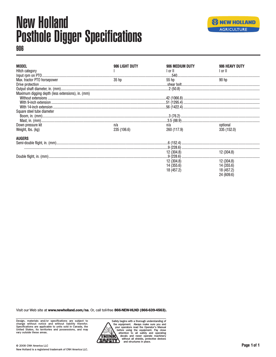
Table of contents
Document Outline
- Table of Contents
- Section 1 Specifications 5
- Section 2 General Information 7
- Section 3 Installation 13
- 3.1 Unpacking the Instrument 13
- 3.2 Selecting the Installation Site 13
- 3.3 Mounting the Sampler 14
- 3.4 Attaching the Intake Line 14
- 3.5 Setting Up the Intake Line and Strainer 15
- 3.6 Choosing Bottles 15
- 3.7 Installing the Full Bottle Shut-Off 15
- 3.8 Power Connections 16
- 3.9 12 V dc 17
- 3.10 Auxiliary Connection 17
- Section 4 Operation 21
- 4.1 Keypad and Key Functions 21
- 4.2 Tips and Techniques for Programming the Instrument 22
- 4.3 Setting the Time and Date 23
- 4.4 Bottle Setup Mode 23
- 4.5 Explanations of Program Messages 24
- 4.6 Data Logging 25
- 4.7 Manual Mode 25
- 4.8 Measurements Triggered by Liquid Levels or Flow 26
- 4.9 Programming the Sampler for Level Control 27
- 4.10 Other Displayed Messages 27
- 4.11 Flow Proportional Operation 28
- Section 5 Maintenance 33
- 5.1 Cleaning the Sampler 33
- 5.2 Pump Tubing Maintenance 33
- 5.3 Upgrades, Repairs, General Maintenance 33
- 5.4 Electrostatic Discharge (ESD) Considerations 33
- 5.5 Internal Maintenance Items 33
- 5.6 Removing and Opening the Controller 33
- 5.7 Re-installing the Bottom Panel 34
- 5.8 Internal Desiccant Module 35
- 5.9 Circuit Board Identification 35
- 5.10 Motor/Gear Box 36
- 5.11 Internal Case Humidity Indicator 36
- 5.12 Internal Case Humidity Indicator 36
- 5.13 Memory Battery 36
- Section 6 Contact Information for U.S.A. & Outside Europe 37
- Section 7 Contact Information for Europe 38
- Section 8 Limited Warranty 39
- Section 9 Parts and Accessories 41
- Section 1 Specifications
- Section 2 General Information
- Section 3 Installation
- 3.1 Unpacking the Instrument
- 3.2 Selecting the Installation Site
- 3.3 Mounting the Sampler
- 3.4 Attaching the Intake Line
- 3.4.1 Vinyl Intake Tubing
- 1. Push one end of the clear flexible PVC (vinyl) tube to the tapered end of the intake strainer, until the tube is within 0.635 cm (¹ in.) of the solid white Teflon strainer body.
- 2. Push the other end of the vinyl tube on to the stainless steel fitting connector end that points away from the pump control housing.
- 3.4.2 Teflon-Lined Polyethylene Intake Line
- 1. Place the stainless steel hose clamp over the stainless steel fitting until it abuts the shoulder of the tubing connector. Secure with a tubing clamp.
- 2. Push the stainless steel fitting into the Teflon-lined tubing until it abuts the shoulder of the stainless steel fitting.
- 3. Slide the stainless steel hose clamp over the silicone tubing, then push the silicone tubing over the stainless steel fitting on the liquid sensor.
- 4. Slide the tubing clamp over the silicone tubing until it is over the stainless steel fitting on the liquid sensor. Tighten to secure.
- 5. Repeat the procedure for the intake strainer.
- 3.4.1 Vinyl Intake Tubing
- 3.5 Setting Up the Intake Line and Strainer
- 3.6 Choosing Bottles
- 3.7 Installing the Full Bottle Shut-Off
- 3.8 Power Connections
- 3.9 12 V dc
- 3.10 Auxiliary Connection
- Table 2 Auxiliary Pin Assignments
- Contact Closures
- Note: The sampler provides 12 V dc on Pin A of the Auxiliary Receptacle and this voltage is pulsed back to Pin C each time the contact closes on the external flow meter. The external flow meter must provide a dry contact closure.
- Note: Older model 4-20 mA interfaces (Cat. No. 913) require correct loop polarity to properly work. The newer generation (Cat. No. 2020 series) interfaces are not sensitive to loop polarity.
- Figure 6 4-20 mA Interface and Pulse Duration Input
- Figure 7 Splitter Interface
- Table 2 Auxiliary Pin Assignments
- Section 4 Operation
- 4.1 Keypad and Key Functions
- 4.2 Tips and Techniques for Programming the Instrument
- 4.3 Setting the Time and Date
- Note: When setting the time and date, the * key causes the display to back up to the previously flashing character.
- 1. Check the real-time clock and date settings by pressing TIME/READ. The display will show the time and date for several seconds: 10:35 AM 24OCT00
- 2. If the time or date are not correct, press TIME/SET. The time and date will appear on the display, with the hour flashing.
- 3. Press the appropriate numerical key(s) for the correct hour. When the correct hour flashes on the display, press YES. This will cause the minutes to flash on the display.
- 4. Using the same procedure, select the correct minutes and press YES. The am/pm indicator will flash.
- 5. If the desired indicator is flashing on the display, press YES. If the desired indicator is not flashing, press NO. This will cause the other indicator to flash.
- 6. Press YES. The month will begin to flash. Select the correct day, month and year using the same procedure as you used to set the time.
- 7. After the correct year has been entered, the display will read "Synchronize Time-enter at Time". Pressing YES will start the clock. The display will read "Clock is Now Set".
- Note: When setting the time and date, the * key causes the display to back up to the previously flashing character.
- 4.4 Bottle Setup Mode
- 1. With the sampler in standby state, press the * key. The display will read “Enter units for bottle volume, milliliters?”.
- 2. Press NO to cause other volume units to appear. When the desired units appear on the display, press YES.
- 3. The display will show "Volume = _ _ _ _ _ mL" (or "Volume = _ _ _ _ _ Gallons"), whichever was chosen in the previous step.
- 4. Enter the volume for the individual sample bottle by pressing the numerical keys.
- 5. Press YES to accept the volume.
- 4.5 Explanations of Program Messages
- 4.6 Data Logging
- 1. To access information, the sampler must be in the "Program Halted" or "Program Complete" standby state.
- 2. Press TIME/READ for two seconds. The display will read "Samples Taken".
- 3. To display the time/date for each sample, press YES. To advance to the next sample time/date, press YES again-and so forth, until all are given.
- 4. To exit this routine, press NO. The time and date of any missed samples are displayed after collected samples.
- 4.7 Manual Mode
- 4.7.1 Manually Operating the Sample Pump
- 1. To manually operate the pump, place the sampler in standby state. The sampler is in standby state when the display reads "Ready to Start", "Program Halted", or "Program Complete".
- 2. To operate the pump, press either the PUMP or PURGE key. This will cause "Manual Mode - Pump/Purge/Clear" to appear on the di...
- 3. To run the pump continuously in either direction without having to hold down the PUMP or PURGE keys, press the * key. This will cause "Lock-Pump/Purge" to appear on the display. Then press either PUMP or PURGE.
- 4. To stop the pump, press STOP PUMP or turn the sampler off with the OFF key. Pressing STOP PUMP returns the display to "Pump/Purge/Clear".
- 5. To exit the manual mode, press CLEAR ENTRY. This returns the sampler to the standby state.
- 4.7.1 Manually Operating the Sample Pump
- 4.8 Measurements Triggered by Liquid Levels or Flow
- 4.9 Programming the Sampler for Level Control
- 4.10 Other Displayed Messages
- 4.11 Flow Proportional Operation
- 4.11.1 How to Calculate Pulses/Counts
- 4.11.1.1 Flow Proportional Sampling Intervals-Using External Pulses
- 1. Determine f, where f represents the flow increment between samples and n represents the total number of samples to be collected.
- 2. Multiply the flow increment between samples, f, by the pulse frequency output of the flow meter (i.e. 1 pulse per 100 gallons...
- Example 1
- Example 2
- Example 3
- Flow Proportional Sampling, External-Using 4-20 mA Signal Converted to Pulses, Flow Signal Interface
- 1. Calculate Q, where Q is the average flow rate (during the sampling program) divided by the maximum flow rate. (The maximum flow rate corresponds to the 20 mA output of the flow meter.)
- 2. Calculate t, where t is defined as a/n; n is the total number of samples collected over a given period of time; and a represents time in minutes, over which n samples are collected.
- 3. Multiply Q x t. Enter the result in the programming step: INTV = _ _ _ _ CNTS.
- Example 1
- Example 2
- Example 3
- Example 4
- Example 5
- 4.11.1.1 Flow Proportional Sampling Intervals-Using External Pulses
- 4.11.1 How to Calculate Pulses/Counts
- Section 5 Maintenance
- 5.1 Cleaning the Sampler
- 5.2 Pump Tubing Maintenance
- 5.3 Upgrades, Repairs, General Maintenance
- 5.4 Electrostatic Discharge (ESD) Considerations
- 5.5 Internal Maintenance Items
- 5.6 Removing and Opening the Controller
- CAUTION Always power the unit OFF and then disconnect all cables from the 900 Composite sampler before removing the controller.
- 1. Turn the unit off by pressing the OFF key.
- 2. Disconnect and remove all cables to the controller housing, including the distributor/full bottle shutoff cable.
- 3. Disconnect all tubing.
- 4. Place the controller, face down, on a cloth-covered workbench to prevent scratching the front panel.
- 5. Inside the Center Section, remove the four screws that fasten the Controller.
- 6. Lift the Center Section off the controller.
- 7. Remove the 17 screws from around the perimeter of the controller back panel.
- 8. Carefully pull open the bottom panel and let the attached connectors swing out of the way.
- 9. If necessary for the repair being performed, unplug the appropriate connectors. Always note each connector location before unplugging anything. Re-installing a plug into the wrong connector can cause extensive damage.
- CAUTION Always power the unit OFF and then disconnect all cables from the 900 Composite sampler before removing the controller.
- 5.7 Re-installing the Bottom Panel
- 5.8 Internal Desiccant Module
- 5.9 Circuit Board Identification
- 5.10 Motor/Gear Box
- 5.11 Internal Case Humidity Indicator
- 5.12 Internal Case Humidity Indicator
- 5.13 Memory Battery
- Section 6 Contact Information for U.S.A. & Outside Europe
- Section 7 Contact Information for Europe
- Section 8 Limited Warranty
- Section 9 Parts and Accessories
- Description Part Number
- 3-way Splitter Assembly 939
- 4-20 mA Interface, 10 ft Cable 2021
- 900 Series Peristaltic Pump Tubing, 15 ft 4600-15
- 900 Series Peristaltic Pump Tubing, 50 ft 4600-50
- 900 Series Peristaltic Pump Tube Insert 8888
- All Weather Refrigerated Cabinet, 115 V ac 3548
- Anchor Kit 8935
- Cascade Sampling for 25-ft Cable 2817
- Desiccant Bag (1 pillow) 8849
- Distributor Arm, 2-and 4-bottle Sampling 8846
- Distributor Arm, 8-bottle Sampling 8845
- Distributor Arm, 24-bottle Sampling 8844
- Door Assembly 8702
- Flow-thru Module 2471
- Humidity Indicator 2660
- Instrument Manual 8837
- Lid Assembly with Latch 8968
- Multi-purpose Full Cable, 10 ft 940
- Multi-purpose Full Cable, 25 ft 540
- Multi-purpose Half Cable, 10 ft 941
- Multi-purpose Half Cable, 25 ft 541
- O-ring, Main Seal 8606
- Pump Tubing, 15 ft, For all distributors and 800 series peristaltic pumps 3866-15
- Pump Tubing, 50 ft, For all distributors and 800 series peristaltic pumps 3866-50
- Strainer, All 316 Stainless Steel, 6.0 in. long x 0.406 in. OD 2071
- Strainer, All 316 Stainless Steel, 7.94 in. long, x 1.0 in. OD 2070
- Strainer, Stainless Steel, 3.9 in. long x 0.406 in. OD 4652
- Strainer, Teflon®/Stainless Steel, 5.5 in. long x 0.875 in. OD 926
- Strainer, Teflon/Stainless Steel, 11.0 in. long x 0.875 in. OD 903
- Synchronizing Sampling for 25-ft Cable 2818
- Teflon-Lined Connection Kit 2186
- Teflon-lined Tubing, 3/8 in., 10 ft 921
- Teflon-lined Tubing, 3/8 in., 25 ft 922
- Teflon-lined Tubing, 3/8 in., 100 ft 925
- Vinyl Intake Tubing, 3/8 in., 25 ft 920
- Vinyl Intake Tubing, 3/8 in., 100 ft 923
- Vinyl Intake Tubing, 3/8 in., 500 ft 924
- Appendix A Programming Flow Chart
- Program Flow Chart
- Lead-Acid (Gel Cell) Batteries
- Nickel-Cadmium Batteries
- Exploded View (1 of 6)
- Exploded View (2 of 6)
- Exploded View (3 of 6)
- Exploded View (4 of 6)
- Exploded View (5 of 6)
- Exploded View (6 of 6)
- Description Part Number
Related manuals for 906


New Manuals
- ZyXEL Communications ZyXEL G-162 Video Gaming Accessories User Manual
- ZyXEL Communications EW103U/A Video Gaming Accessories User Manual
- Western Telematic RSM-8 Video Gaming Accessories User Manual
- Western Telematic RSM-32DC Video Gaming Accessories User Manual
- Western Telematic RSM-32 Video Gaming Accessories User Manual
- Western Telematic RSM-16DC Video Gaming Accessories User Manual
- Western Telematic RSM-16 Video Gaming Accessories User Manual
- Viking Electronics FBI-1A Video Gaming Accessories User Manual
- Viking Electronics DVA-500A Video Gaming Accessories User Manual
- Viking Electronics DVA-3003 Video Gaming Accessories User Manual
- Viking Electronics DVA-2W Video Gaming Accessories User Manual
- Viking Electronics DVA- 1003B Video Gaming Accessories User Manual