
624J WH Guide
User manual for 624J WH
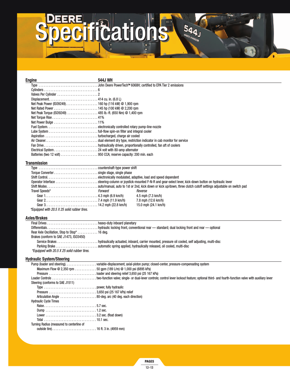


Table of contents 01-Chapter1 Product Overview.pdf 02-Chapter2 LPU Modules.pdf 03-Chapter3 Installation Preparations.pdf 04-Chapter4 Switch Installation.pdf 05-Chapter5 System Debugging.pdf 06-Chapter6 Switch Monitoring and Maintenance.pdf 07-AppendixA Engineering Labels for Cables.pdf 08-AppendixB Installation of B68 Cabinet.pdf 09-AppendixC Lightning Protection of the Switch.pdf
Document Outline
- Chapter 4 Switch Installation
- 4.1 Confirming Installation Preparation
- 4.2 Installation Flow
- 4.3 Mounting the Switch in User-Supplied Cabinet
- 4.4 Mounting the Switch in B68 Cabinet
- 4.5 Connecting PGND Wire and Power Cord
- 4.6 Installing the AC Power Distribution Box
- 4.7 Installing DC Power Distribution Box
- 4.8 Installing Cabling Rack
- 4.9 Installing Fan Tray
- 4.10 Installing LPU
- 4.11 Connecting Interface Cables
- 4.12 Cable Routing Recommendations
- 4.13 Cable Management
- 4.14 Verifying the Installation
- Chapter 6 Switch Monitoring and Maintenance
- 6.1 Monitoring the Switch
- 6.2 Hardware Maintenance
- 6.3 Software Upgrade
- 6.4 Password Loss
- Appendix A Engineering Labels for Cables
- A.1 Introduction to Labels
- A.2 Engineering Labels for Ethernet Cables
- A.3 Engineering Labels for Optical Fibers
- A.4 Engineering Labels for Power Cables
- Appendix B Installation of B68 Cabinet
- B.1 Installation Overview
- B.2 Cabinet Installation on the Cement Ground
- B.3 Cabinet Installation on Raised Floor
- B.3.1 Introduction to Support and Slide Rail
- B.3.2 Installation Flow
- B.3.3 Support Positioning
- B.3.4 Installation of Support and Slide Rail
- B.3.5 Installing Supporting Accessories of Raised Floor
- B.3.6 Cabinet Leveling
- B.3.7 Cabinet Combination Connection
- B.3.8 Cabinet Fastening
- B.3.9 Insulation Test
- B.3.10 Floor Recovery
- B.4 Quakeproof Reinforcement of Cabinet
Related manuals for 624J WH


New Manuals
- ZyXEL Communications ZyXEL G-162 Video Gaming Accessories User Manual
- ZyXEL Communications EW103U/A Video Gaming Accessories User Manual
- Western Telematic RSM-8 Video Gaming Accessories User Manual
- Western Telematic RSM-32DC Video Gaming Accessories User Manual
- Western Telematic RSM-32 Video Gaming Accessories User Manual
- Western Telematic RSM-16DC Video Gaming Accessories User Manual
- Western Telematic RSM-16 Video Gaming Accessories User Manual
- Viking Electronics FBI-1A Video Gaming Accessories User Manual
- Viking Electronics DVA-500A Video Gaming Accessories User Manual
- Viking Electronics DVA-3003 Video Gaming Accessories User Manual
- Viking Electronics DVA-2W Video Gaming Accessories User Manual
- Viking Electronics DVA- 1003B Video Gaming Accessories User Manual