
5900 Guide
User manual for 5900
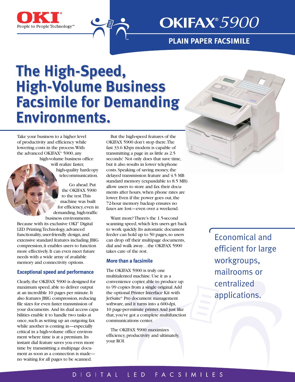

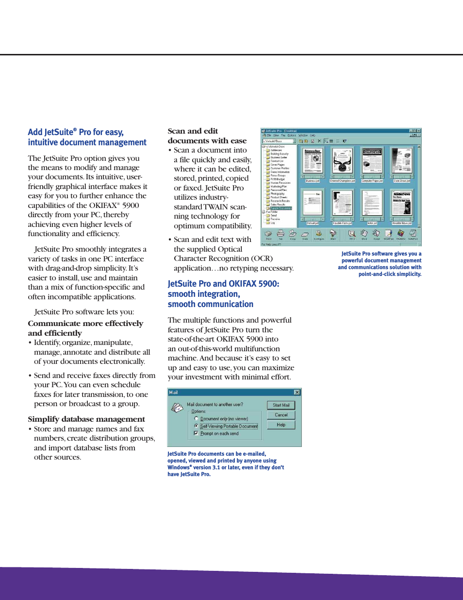

Table of contents
Document Outline
- 1. Pin Descriptions
- 2. Typical Connection Diagrams
- 3. Characteristic and Specification Tables
- Recommended Operating Conditions
- Absolute Maximum Ratings
- Analog Input Characteristics
- ADC Digital Filter Characteristics
- HP Output Characteristics
- Line Output Characteristics
- Analog Passthrough Characteristics
- Combined DAC Interpolation & On-Chip Analog FIlter Response
- Switching Specifications - Serial Port
- Switching Specifications - I²C Control Port
- Switching Characteristics - SPI Control Port
- Analog Output Attenuation Characteristics
- DC Characteristics
- Digital Interface Specifications & Characteristics
- Power Consumption - All Supplies = 1.8 V
- Power Consumption - All Supplies = 2.5 V
- 4. Applications
- 4.1 Overview
- 4.2 Analog Inputs
- 4.3 Analog In to Analog Out Passthrough
- 4.4 Analog Outputs
- 4.5 Class H Amplifier
- 4.6 Beep Generator
- 4.7 Limiter
- 4.8 Serial Port Clocking
- 4.9 Digital Interface Format
- 4.10 Initialization
- 4.11 Recommended DAC to HP or Line Power Sequence
- 4.12 Recommended PGA to HP or Line Power Sequence (Analog Passthrough)
- 4.13 Control Port Operation
- 5. Register Quick Reference
- 6. Register Description
- 6.1 Device I.D. Register (Address 01h) (Read Only)
- 6.2 Device Revision Register (Address 02h) (Read Only)
- 6.3 Power Control 1 (Address 03h)
- 6.4 Power Control 2 (Address 04h)
- 6.5 Clocking Control 1 (Address 05h)
- 6.6 Clocking Control 2 (Address 06h)
- 6.7 Serial Format (Address 07h)
- 6.8 Class H Control (Address 08h)
- 6.9 Misc. Control (Address 09h)
- 6.10 Status (Address 0Ah) (Read Only)
- 6.11 Playback Control (Address 0Bh)
- 6.12 DSP Mute Controls (Address 0Ch)
- 6.13 ADCx Mixer Volume: ADCA (Address 0Dh) & ADCB (Address 0Eh)
- 6.14 PCMx Mixer Volume: PCMA (Address 0Fh) & PCMB (Address 10h)
- 6.15 Analog Input Advisory Volume (Address 11h)
- 6.16 Digital Input Advisory Volume (Address 12h)
- 6.17 Master Volume Control: MSTA (Address 13h) & MSTB (Address 14h)
- 6.18 Beep Frequency & On Time (Address 15h)
- 6.19 Beep Volume & Off Time (Address 16h)
- 6.20 Beep & Tone Configuration (Address 17h)
- 6.21 Tone Control (Address 18h)
- 6.22 ADC & PCM Channel Mixer (Address 19h)
- 6.23 AIN Reference Configuration, ADC MUX (Address 1Ah)
- 6.24 HPF Control (Address 1Bh)
- 6.25 Misc. ADC Control (Address 1Ch)
- 6.26 Gain & Bias Control (Address 1Dh)
- 6.27 PGA x MUX, Volume: PGA A (Address 1Eh) & PGA B (Address 1Fh)
- 6.28 ADCx Attenuator Control: ADCAATT (Address 20h) & ADCBATT (Address 21h)
- 6.29 ALC Enable & Attack Rate (Address 22h)
- 6.30 ALC Release Rate (Address 23h)
- 6.31 ALC Threshold (Address 24h)
- 6.32 Noise Gate Control (Address 25h)
- 6.33 ALC and Limiter Soft Ramp, Zero Cross Disables (Address 26h)
- 6.34 Automute, Line & HP MUX (Address 27h)
- 6.35 Headphone Volume Control: HPA (Address 28h) & HPB (Address 29h)
- 6.36 Line Volume Control: LINEA (Address 2Ah) & LINEB (Address 2Bh)
- 6.37 Limiter Min/Max Thresholds (Address 2Ch)
- 6.38 Limiter Control, Release Rate (Address 2Dh)
- 6.39 Limiter Attack Rate (Address 2Eh)
- 7. PCB Layout Considerations
- 8. Analog Volume Non-Linearity (DNL & INL)
- 9. ADC & DAC Digital Filters
- 10. Parameter Definitions
- 11. Package Dimensions
- 12. Ordering Information
- 13. References
- 14. Revision History
Related manuals for 5900
New Manuals
- ZyXEL Communications ZyXEL G-162 Video Gaming Accessories User Manual
- ZyXEL Communications EW103U/A Video Gaming Accessories User Manual
- Western Telematic RSM-8 Video Gaming Accessories User Manual
- Western Telematic RSM-32DC Video Gaming Accessories User Manual
- Western Telematic RSM-32 Video Gaming Accessories User Manual
- Western Telematic RSM-16DC Video Gaming Accessories User Manual
- Western Telematic RSM-16 Video Gaming Accessories User Manual
- Viking Electronics FBI-1A Video Gaming Accessories User Manual
- Viking Electronics DVA-500A Video Gaming Accessories User Manual
- Viking Electronics DVA-3003 Video Gaming Accessories User Manual
- Viking Electronics DVA-2W Video Gaming Accessories User Manual
- Viking Electronics DVA- 1003B Video Gaming Accessories User Manual