
5130GM Guide
User manual for 5130GM


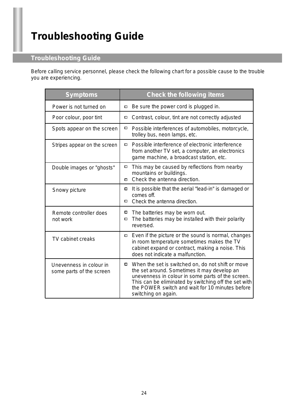
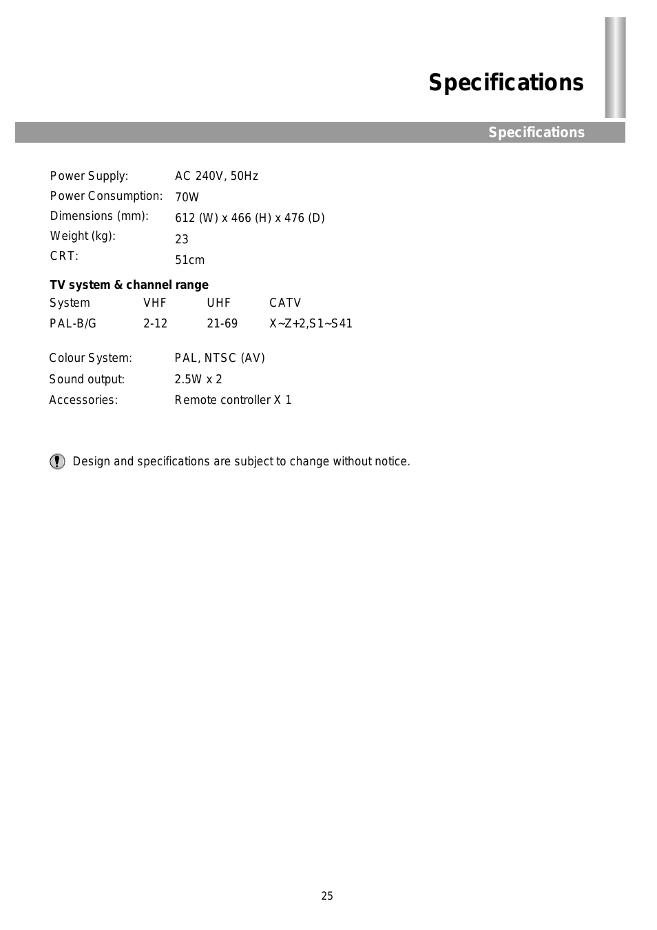

Table of contents
Document Outline
- Contents
- Preface
- Product Overview
- Figure 1-1 Cisco Secure Router 520 Ethernet-to-Ethernet Wireless Router-Front Panel
- Figure 1-2 Cisco Secure Router 520 Series Router-Back Panel
- Figure 1-3 Cisco Secure Router 520 ADSL-over-POTS Wireless Router-Front Panel
- Figure 1-4 Cisco Secure Router 520 ADSL-over-ISDN Wireless Router-Front Panel
- Figure 1-5 Serial Number Location on the Back of the Cisco Secure Router 520 Series Router
- Table 1-1 LED Indicators on the Routers
- Table 1-2 Cisco Secure Router 520 Series Feature Summary
- Preinstallation Information
- Step 1 Wear an ESD-preventive wrist strap that you provide, ensuring that it makes good skin contact.
- Step 2 Do not touch any exposed contact pins or connector shells of interface ports that do not have a cable attached.
- Step 1 Obtain a broadband or Ethernet connection from your service provider.
- Step 2 Remove the cables and product documentation from the plastic bag. Remove the router power adapter and the black power cord from the accessory kit.
- Step 3 If you ordered a wireless router, remove the antenna from the box.
- Step 4 Gather the Ethernet devices to be connected to the router: servers, workstations, or PCs. Make sure that there is a network interface card (NIC) in each device for connecting to the Ethernet ports.
- Step 5 If you plan to configure the software by using Cisco IOS commands and the console port, provide an ASCII terminal or a PC that is running terminal emulation software to connect to the console port.
- Step 6 If you plan to connect a modem, provide the modem and modem cable.
- Step 7 If you plan to use the cable-lock feature, provide a Kensington or equivalent locking cable.
- Step 8 Read the safety warnings (see the “Safety Warnings and Guidelines” section on page 2-1) and information about preventing damage to the router (see the “Preventing Damage to the Router” section on page 2-3).
- Router Mounting Procedures
- Step 1 Attach the antenna to the reverse-polarity threaded Neill-Concelman (RP-TNC) connector on the front of the router, and then tighten the antenna.
- Step 2 Orient the antenna vertically (straight up).
- Step 1 Place the unit upside-down on the flat surface.
- Step 2 Attach the four rubber pads to the recessed areas on the bottom of the unit.
- Step 3 Place the unit right-side-up on the flat surface.
- Step 4 If you have a wireless router, connect the radio antenna to the router (see the “Connecting a Radio Antenna to a Wireless Router” section on page 3-1).
- Step 5 Place the power supply unit on a desktop near an AC power source. Do not stack the power supply on the router.
- Step 1 If you have a wireless router, connect the radio antenna to the router (see the “Connecting a Radio Antenna to a Wireless Router” section on page 3-1).
- Step 2 Position the router on the wall to determine where to attach the two mounting screws. Make sure the distance between the screws is 8.25 in. (see Figure 3-1 on page 3-2).
- Step 3 Mount the router on a wall stud or a hollow wall. Perform one of the following, as appropriate:
- Step 4 Insert the wood screws or wall anchors (whichever you used) into the mounting-screw holes on the router. Mount the router vertically, with the front panel facing upward and the connection to the power cord facing downward.
- Step 1 If you have a wireless router, first connect the radio antenna to the router (see the “Connecting a Radio Antenna to a Wireless Router” section on page 3-1).
- Step 2 Using a number 2 Phillips screwdriver and four screws, install a bracket to each side of the router as shown in Figure 3-2.
- Step 3 Using two pairs of screws on each side (supplied with the rack) attach the router to a 19-inch rack. Install the lower pa...
- Router Installation
- Figure 4-1 Typical Installation of a Cisco Secure Router 520 Ethernet-to-Ethernet Router
- Step 1 If you have a wireless router, first connect the radio antenna to the router. See the “Connecting a Radio Antenna to a Wireless Router” section on page 3-1.
- Step 2 Connect the server, PC, or workstation to the router. See the “Connecting a Server, PC, or Workstation” section on page 4-6.
- Step 3 (Optional) If you need to connect more than four PCs, connect an external Ethernet switch to the router’s built-in switch. See the “Connecting an External Ethernet Switch (Optional)” section on page 4-7.
- Step 4 Connect a broadband modem to the router for Internet connection. See the “Connecting a Broadband Modem” section on page 4-8.
- Step 5 Connect the AC adapter to the router. See the “Connecting the AC Adapter” section on page 4-12.
- Step 6 To configure the router software by using the command-line interface (CLI) or to troubleshoot problems, connect a terminal or PC to the console port. See the “Connecting a Terminal or PC to the Console Port” section on page 4-14.
- Step 7 (Optional) To use the console port as a backup link to the WAN port in case the ADSL service goes down, connect an analog modem to the console port. See the “Connecting an Asynchronous Modem to the Console Port” section on page 4-14.
- Step 1 If you have a wireless router, first connect the radio antenna to the router. See the “Connecting a Radio Antenna to a Wireless Router” section on page 3-1.
- Step 2 Connect the server, PC, or workstation to the router. See the “Connecting a Server, PC, or Workstation” section on page 4-6.
- Step 3 (Optional) If you need to connect more than four PCs, connect an external Ethernet switch to the router’s built-in switch. See the “Connecting an External Ethernet Switch (Optional)” section on page 4-7.
- Step 4 Connect the ADSL line. See the “Connecting an ADSL Line-ADSLoPOTS Port” section on page 4-9.
- Step 5 Connect the AC adapter to the router. See the “Connecting the AC Adapter” section on page 4-12.
- Step 6 To configure the router software by using the command-line interface (CLI) or to troubleshoot problems, connect a terminal or PC to the console port. See the “Connecting a Terminal or PC to the Console Port” section on page 4-14.
- Step 7 (Optional) To use the console port as a backup link to the WAN port in case the ADSL service goes down, connect an analog modem to the console port. See the “Connecting an Asynchronous Modem to the Console Port” section on page 4-14.
- Step 1 If you have a wireless router, first connect the radio antenna to the router. See the “Connecting a Radio Antenna to a Wireless Router” section on page 3-1.
- Step 2 Connect the server, PC, or workstation to the router. See the “Connecting a Server, PC, or Workstation” section on page 4-6.
- Step 3 (Optional) If you need to connect more than four PCs, connect an external Ethernet switch to the router’s built-in switch. See the “Connecting an External Ethernet Switch (Optional)” section on page 4-7.
- Step 4 Connect the ADSL line. See the “Connecting an ADSL Line-ADSLoISDN Port” section on page 4-10.
- Step 5 Connect the AC adapter to the router. See the “Connecting the AC Adapter” section on page 4-12.
- Step 6 To configure the router software by using the command-line interface (CLI) or to troubleshoot problems, connect a terminal or PC to the console port. See the “Connecting a Terminal or PC to the Console Port” section on page 4-14.
- Step 7 (Optional) To use the console port as a backup link to the WAN port in case the ADSL service goes down, connect an analog modem to the console port. See the “Connecting an Asynchronous Modem to the Console Port” section on page 4-14.
- Step 1 Connect one end of the yellow Ethernet cable to a built-in Ethernet switch port on the router.
- Step 2 Connect the other end of the cable to the RJ-45 port on the network interface card (NIC) that is installed in the PC, server, or workstation.
- Step 3 (Optional) Connect additional servers, PCs, or workstations to the other built-in Ethernet switch ports.
- Step 1 Connect one end of the yellow Ethernet cable to a built-in Ethernet switch port on the router.
- Step 2 Connect the other end of the cable to an available port on the Ethernet switch to add an additional Ethernet connection.
- Step 3 Turn on the Ethernet switch.
- Step 1 Connect one end of the yellow cable to the Ethernet WAN FE4 port.
- Step 2 Connect the other end of the cable to an available port on the modem.
- Step 3 Turn on the broadband modem.
- Step 1 Connect one end of the power supply cable into the input jack on the router.
- Step 2 Connect the other end of the power supply cable to the AC adapter.
- Step 3 Plug the power cord of the AC adapter into an electrical outlet.
- Step 1 Connect the RJ-45 connector on the light blue cable to the router’s console port.
- Step 2 Connect the DB-9 connector to a terminal or PC.
- Step 1 Connect the RJ-45 end of the router modem cable to the console port.
- Step 2 Connect the DB-25 connector end of the router modem cable to an available port on the asynchronous modem.
- Step 3 Connect one end of the RJ-11 telephone cable to a wall jack, and then connect the other end of the RJ-11 cable to the modem.
- Step 4 (Optional) Connect one end of an RJ-11 telephone cable to a telephone, fax, or other device, and then connect the other end of the RJ-11 cable to the modem.
- Troubleshooting
- Specifications
- Index
Related manuals for 5130GM

New Manuals
- ZyXEL Communications ZyXEL G-162 Video Gaming Accessories User Manual
- ZyXEL Communications EW103U/A Video Gaming Accessories User Manual
- Western Telematic RSM-8 Video Gaming Accessories User Manual
- Western Telematic RSM-32DC Video Gaming Accessories User Manual
- Western Telematic RSM-32 Video Gaming Accessories User Manual
- Western Telematic RSM-16DC Video Gaming Accessories User Manual
- Western Telematic RSM-16 Video Gaming Accessories User Manual
- Viking Electronics FBI-1A Video Gaming Accessories User Manual
- Viking Electronics DVA-500A Video Gaming Accessories User Manual
- Viking Electronics DVA-3003 Video Gaming Accessories User Manual
- Viking Electronics DVA-2W Video Gaming Accessories User Manual
- Viking Electronics DVA- 1003B Video Gaming Accessories User Manual