
42MT Lever Housing Guide
User manual for 42MT Lever Housing
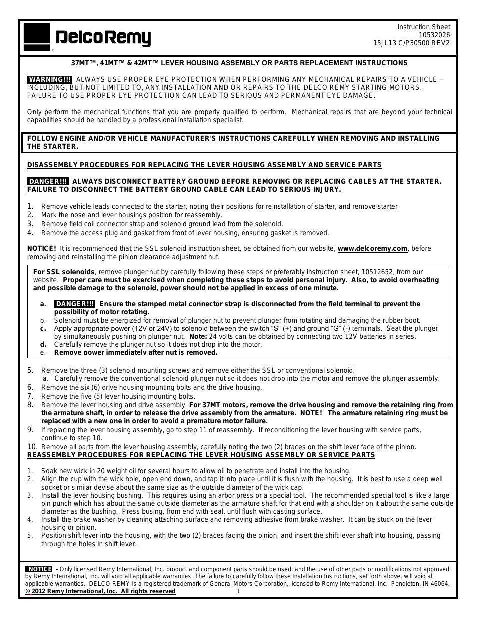


Table of contents
Document Outline
- Model
- 10VP
- 15VP
- 20VP
- 3120728
- June 14, 2001
- SERVICE & MAINTENANCE
- 3120728
- This page left intentionally blank.
- FOREWORD
- The purpose of this manual is to provide users with the operating procedures essential for the pr...
- BECAUSE THE MANUFACTURER HAS NO DIRECT CONTROL OVER MACHINE APPLICATION AND OPERATION, PROPER SAF...
- ALL INSTRUCTIONS IN THIS MANUAL ARE BASED ON THE USE OF THE MACHINE UNDER PROPER OPERATING CONDIT...
- THIS "SAFETY ALERT SYMBOL" IS USED TO CALL ATTENTION TO POTENTIAL HAZARDS WHICH MAY LEAD TO SERIO...
- Safety of personnel and proper use of the machine are of primary concern, DANGER, WARNING, CAUTIO...
- This page intentionally left blank
- Introduction - Maintenance safety precautions
- a. GENERAL
- This section contains the general safety precautions which must be observed during maintenance of...
- The specific precautions to be observed during machine maintenance are inserted at the appropriat...
- Your safety, and that of others, is the first consideration when engaging in the maintenance of e...
- b. HYDRAULIC SYSTEM SAFETY
- c. MAINTENANCE
- This page intentionally left blank
- a. GENERAL
- Effectivity Changes
- LIST OF FIGURES
- LIST OF TABLES
- Section 1. specifications
- 1.1 Capacities
- 1.2 Component Data
- Hydraulic Pump/Pump Motor Assembly
- Pump Motor - 24 Volt DC motor
- Pump Displacement –
- 10 & 15VP – .098 cu. in./rev. (1.6cc/rev.)
- 20VP – .049 cu. in./rev. (0.8cc/rev )
- Pump Output (Max.) –
- 10 & 15VP - 1.20 gpm @ 2200 psi
- 20VP – 0.65 gpm @ 2200 psi
- Hydraulic System Pressure Setting –
- 10 & 15VP - 1000 psi (68.95 bar)
- 20VP - 2500 psi (172.3 bar)
- Rear Wheel Drive Motors
- Batteries/Battery Charger
- Hydraulic Pump/Pump Motor Assembly
- 1.3 Performance Data
- Platform Capacity(All Platforms except Extendible)
- Extendible Platform Capacity
- Platform Size
- Machine Height (In Stowed Position)
- Base Footprint
- Max. Platform Height (mast extended)
- Platform Working Height (average)
- Machine Drive Speed (max.)*
- Amperage Draw (average)
- Interlock Switch Operating Conditions
- 1.4 Torque Requirements
- 1.5 Lubrication
- Hydraulic Oil
- Hydraulic oils must have anti-wear qualities at least to API Service Classification GL-3, and suf...
- For cold weather applications, i.e. when temperatures remain consistently below +20˚F (–7˚C) JLG ...
- Aside from JLG recommendations, it is not advisable to mix oils of different brands or types, as ...
- Table 1-2. Hydraulic Oil Operating Range
- Lubrication Specifications
- Hydraulic Oil
- 1.6 Hydraulic Pressure Adjustment
- Adjust system pressure so that platform will raise with rated capacity in platform.
- The following are recommended factory pressure settings;
- VP10, VP15 – 1000 psi VP20 – 2500 psi
- Turning adjustment screw clockwise increases system pressure, turning screw counterclockwise decr...
- Make pressure adjustment with oil at normal operating temperature. If pressure is set when oil is...
- Connect pressure gauge as shown in Figure 1-2., Hydraulic Pressure Gauge Installation.
- Select a T-Fitting to exactly match the thread size of the pump (.562 x 18 THD), pressure line (....
- 1.7 Cylinder Specifications
- 1.8 Serial Number Location
- This page intentionally left blank
- Section 2. SERVICE PROCEDURES
- 2.1 General
- 2.2 Servicing and Maintenance Guidelines
- General
- Safety and Workmanship
- Cleanliness
- The most important single item in preserving the long service life of a machine is to keep dirt a...
- At any time when oil lines are disconnected, clear adjacent areas as well as the openings and fit...
- Clean and inspect all parts during servicing or maintenance, and assure that all passages and ope...
- Components Removal and Installation
- Use adjustable lifting devices, whenever possible, if mechanical assistance is required. All slin...
- Should it be necessary to remove a component on an angle, keep in mind that the capacity of an ey...
- If a part resists removal, check to see whether all nuts, bolts, cables, brackets, wiring, etc., ...
- Component Disassembly and Reassembly
- Pressure-Fit Parts
- Bearings
- When a bearing is removed, cover it to keep out dirt and abrasives. Clean bearings in nonflammabl...
- Discard bearings if the races and balls (or rollers) are pitted, scored, or burned.
- If bearing is found to be serviceable, apply a light coat of oil and wrap it in clean (waxed) pap...
- Lubricate new or used serviceable bearings before installation. When pressing a bearing into a re...
- Gaskets
- Bolt Usage and Torque Application
- Hydraulic Lines and Electrical Wiring
- Hydraulic System
- Lubrication and Servicing
- Batteries
- Mast Chain Inspection Procedure
- .50" pitch
- 12" or 24 pitches
- .24 in./12 in. span
- .625 pitch
- 15" or 24 pitches
- .30 in./15 in. span
- Fatigue Cracks: Fatigue is a phenomenon that affects most metals, and is the most common cause of...
- Tight Joints: All joints in the leaf chain should flex freely. On leaf chain, tight joints are us...
- Oil rusty chains, and replace chains with bent or peened chain components. Keep chains lubricated.
- Protruding or Turned Pins: Chains operating with inadequate lube generate tremendous friction bet...
- Chain Anchors and Sheaves: An inspection of the chain must include a close examination of chain a...
- Inspect the sheaves, sheave bearings, sheave grooves and pins for extreme wear, replace as necess...
- Mast Cable Inspection Procedure
- The periodic inspection shall cover the entire length of the cable. The inspection frequency shal...
- Only the surface wires of the cable require inspection, do not attempt to open the cable. Any det...
- Mast cables must be replaced after machine has been in service for five (5) years, regardless of ...
- Conditions such as the following shall be sufficient reason for questioning continual use of the ...
- 1. In running ropes, six randomly distributed broken wires in one lay or three broken wires in on...
- 2. One outer wire broken at the point of contact with the core of the rope which has worked its w...
- 3. Wear of one-third the original diameter of outside individual wires.
- 4. Kinking, crushing, birdcaging or any other damage resulting in distortion of the rope structure.
- 5. Evidence of any heat damage from any cause.
- 6. Reductions from nominal diameter of more than;
- Also check for cracked, bent, worn, severely corroded, or improperly installed cable ends.
- Inspect sheaves, sheave grooves, and sheave pins for excessive wear, replace as necessary.
- 2.3 Lubrication Information
- Hydraulic System
- The primary enemy of a hydraulic system is contamination. Contaminants enter the system by variou...
- The design and manufacturing tolerances of the component working parts are very close, therefore,...
- Cloudy oils indicate a high moisture content which permits organic growth, resulting in oxidation...
- It is not advisable to mix oils of different brands or types, as they may not contain the same re...
- Hydraulic Oil
- Changing Hydraulic Oil
- Use of any of the recommended hydraulic oils eliminates the need for changing the oil on a regula...
- Use every precaution to keep the hydraulic oil clean. If the oil must be poured from the original...
- While the unit is shut down, a good preventive maintenance measure is to make a thorough inspecti...
- Lubrication Specifications
- Hydraulic System
- 2.4 Positioning Lift for Access to Components Located Under The Base Frame
- Access to the underside of the VP lift can be obtained by lifting the machine with a fork lift tr...
- Lifting with a Fork Truck (See Figure 2-1.)
- 1. Choose a fork lift truck capable of safely handling the full weight of the machine.
- 2. Locate work area on a firm, level surface.
- 3. When lifting with a fork truck, lift only using the fork lift-truck pockets running the length...
- 4. After lifting machine to desired work height, place support stands under the machine. The supp...
- 2.5 Drive motor component Service procedures
- Torque Limiting Clutch Maintenance
- Visual Inspection and Limiting Torque Checking Procedure
- 1. Locate the machine on a firm level surface.
- 2. Carefully raise the lift to gain access to the underside of the base frame. Refer to Section 2...
- 3. Locate the clutch assembly on each rear drive axle and check for the following;
- a. Check the coupling chains for any loose or missing parts, i.e. pins, links, etc., replace if n...
- b. Check that the allen-head set screws on the (large) clutch adjusting nut are in place and secu...
- c. Check for any debris wedged in or wrapped around the clutch coupling chains and axle shafts. R...
- Checking Clutch - Torque Setting (ft. lb.)
- 1. Remove the drive wheels from the drive axles.
- 2. Select a torque wrench capable of setting a torque of at least 185 ft. lb. Insert special tool...
- 3. Slide the tool onto the end of the drive axle aligning the key on the axle shaft (install key ...
- 4. Turn the torque wrench and note the torque setting when the torque limiting clutch releases. T...
- 5. If torque setting is OK, re-install the wheels and lower machine, IF NOT, see the following note.
- Torque Limiting Clutch Adjustment
- 1. Loosen the two (2) adjusting nut setscrews located on the large adjusting nut on the clutch as...
- 2. Hold the drive axle steady using service tool (P/N- 0080229) and the torque wrench used to che...
- 3. Depending on how far off the original torque setting was (see note at beginning of this proced...
- 4. When proper torque setting is achieved, re-tighten the two (2) adjusting nut, setscrews.
- 5. Re-install the drive wheels, remove the jack stand and lower the machine to ground.
- Drive Motor Brake Adjustment/Removal
- (See Figure 2-4. & Figure 2-5.)
- Mounted onto the front of each drive motor housing is a brake assembly. The brakes are normally E...
- Operation (See Figure 2-4. & Figure 2-5.)
- When the magnetic coil is not energized (brake on), the armature plate is pushed away from the ma...
- A correctly adjusted brake will ideally have a measurment of approximately .006" (but will operat...
- Never allow any type of lubricant (oil, grease, hydraulic fluid, etc.) to come in contact with th...
- Checking/Adjusting Armature Plate Gap Setting
- 1. First inspect that all parts of the brake assembly are tight and secure. Tighten as necessary.
- 2. Inspect the brake for any debris which may be lodged in the air gap between the armature plate...
- 3. With the brakes ENGAGED measure the air gap between the armature plate and the magnetic coil h...
- 4. If the air gap falls outside the maximum allowable setting of .010" the friction disk has worn...
- 5. It the air gap is below the minimum allowable setting of .004", recheck the areas between the ...
- Manual Release Arm - Screw Adjustment
- 1. With the brakes ENGAGED (brakes on) the air gap under the head of the manual release arm screw...
- 2. With the brakes electrically RELEASED (brakes off) the air gap under the screw head increases ...
- Brake Assembly Removal
- 1. Lift the machine to gain access to the underside (See Section 2-4., "Positioning Lift For Acce...
- 2. Disconnect the brake magnetic coil wiring connector and the brake limit (micro) switch wiring ...
- 3. Disconnect the manual brake release cable from the manual brake release arm attached to the br...
- 4. Lower machine back down to ground level.
- 5. Using the Ground Control Switch, raise the platform to gain access to the brake assemblies mou...
- 6. Remove the four (4) hex cap screws securing the brake assembly to the end of the drive motor a...
- Brake Assembly Installation
- 1. Guide the manual release lever, brake coil and brake limit switch wiring connectors through th...
- 2. If necessary, manually release the brake disk using the manual release lever to allow the brak...
- 3. Secure the brake assembly to the drive motor using four (4) hex cap screws with washers. Torqu...
- 4. Lift the machine to gain access to the underside (See Section 2-4., "Positioning Lift For Acce...
- 5. Reconnect the brake coil and brake limit switch wiring connectors to their respective wiring h...
- 6. Reconnect the manual release brake cable to the manual release lever (Y shaped lever) and adju...
- Drive Motor Removal
- (See Figure 2-7.)
- The VP drive motors consist of three sections, the gear box atttached to the rear of the drive mo...
- 1. Disconnect the positive battery terminal from the left side battery.
- 2. Remove the rear plate weldment from the machine, (plate with the tie down lug) and set aside. ...
- 3. Carefully raise the lift to gain access to the underside of the base frame. Refer to Section 2...
- 4. Remove the remaining two (2) bolts attaching the motor cover to the base frame and set it aside.
- 5. Disconnect the wiring connectors to the drive motor and the brake assembly on either or both s...
- 6. Disconnect the manual release brake cable from the brake assembly arm on either or both drive ...
- 7. Remove the one (1) bolt, nut, and two (2) washers from the front of the drive motor mounting p...
- 8. While holding the drive motor in place, remove the remaining two (2) bolts with washers holdin...
- 9. Slide the drive motor and torque limiting clutch assembly towards the center of the machine, s...
- 10. Move drive motor assembly and torque limiting clutch to a suitable work bench for disassembly.
- 11. Carefully remove the four (4) nuts and washers (outer most holes on the drive assembly weldme...
- 12. Lower the drive assembly and place on a suitable work surface.
- Gear Box Disassembly/Assembly
- (See Figure 2-8.)
- The drive motor gear box is mounted on the rear of each drive motor transferring power from the e...
- Gear Box Disassembly (See Figure 2-8.)
- 1. Remove the drive motor/gear box/brake assembly from the machine using the procedure outlined p...
- 2. Remove the four (4) hex cap screws securing the side cover to the gear box housing, and remove...
- 3. Remove the wave washers from atop the large and small bearings and lay inside their respective...
- 4. Using a suitable catch container, drain the gear oil from the gear box housing.
- 5. Remove the drive shaft assembly from the housing. Place the drive motor/gear box assembly on a...
- 6. With the open surface of the housing properly supported, carefully press the drive shaft down ...
- 7. To remove the large (47mm) (cover side) bearing and (housing side) bearing from the drive shaf...
- 8. To remove the small (32mm) bearing(s) from the gear (brass) and pinion assembly, use a suitabl...
- 9. To remove the (brass) worm gear from the pinion assembly, use a suitable hydraulic press and p...
- 10. Inspect the drive shaft seal for cuts, cracks and wear, or if showing signs of leakage. Repla...
- Gear/Pinion Shaft Assembly (See Figure 2-9.)
- 1. L
Related manuals for 42MT Lever Housing
New Manuals
- ZyXEL Communications ZyXEL G-162 Video Gaming Accessories User Manual
- ZyXEL Communications EW103U/A Video Gaming Accessories User Manual
- Western Telematic RSM-8 Video Gaming Accessories User Manual
- Western Telematic RSM-32DC Video Gaming Accessories User Manual
- Western Telematic RSM-32 Video Gaming Accessories User Manual
- Western Telematic RSM-16DC Video Gaming Accessories User Manual
- Western Telematic RSM-16 Video Gaming Accessories User Manual
- Viking Electronics FBI-1A Video Gaming Accessories User Manual
- Viking Electronics DVA-500A Video Gaming Accessories User Manual
- Viking Electronics DVA-3003 Video Gaming Accessories User Manual
- Viking Electronics DVA-2W Video Gaming Accessories User Manual
- Viking Electronics DVA- 1003B Video Gaming Accessories User Manual