
1000 Series Drive Option - Digital Output Installation Guide
User manual for 1000 Series Drive Option - Digital Output Installation
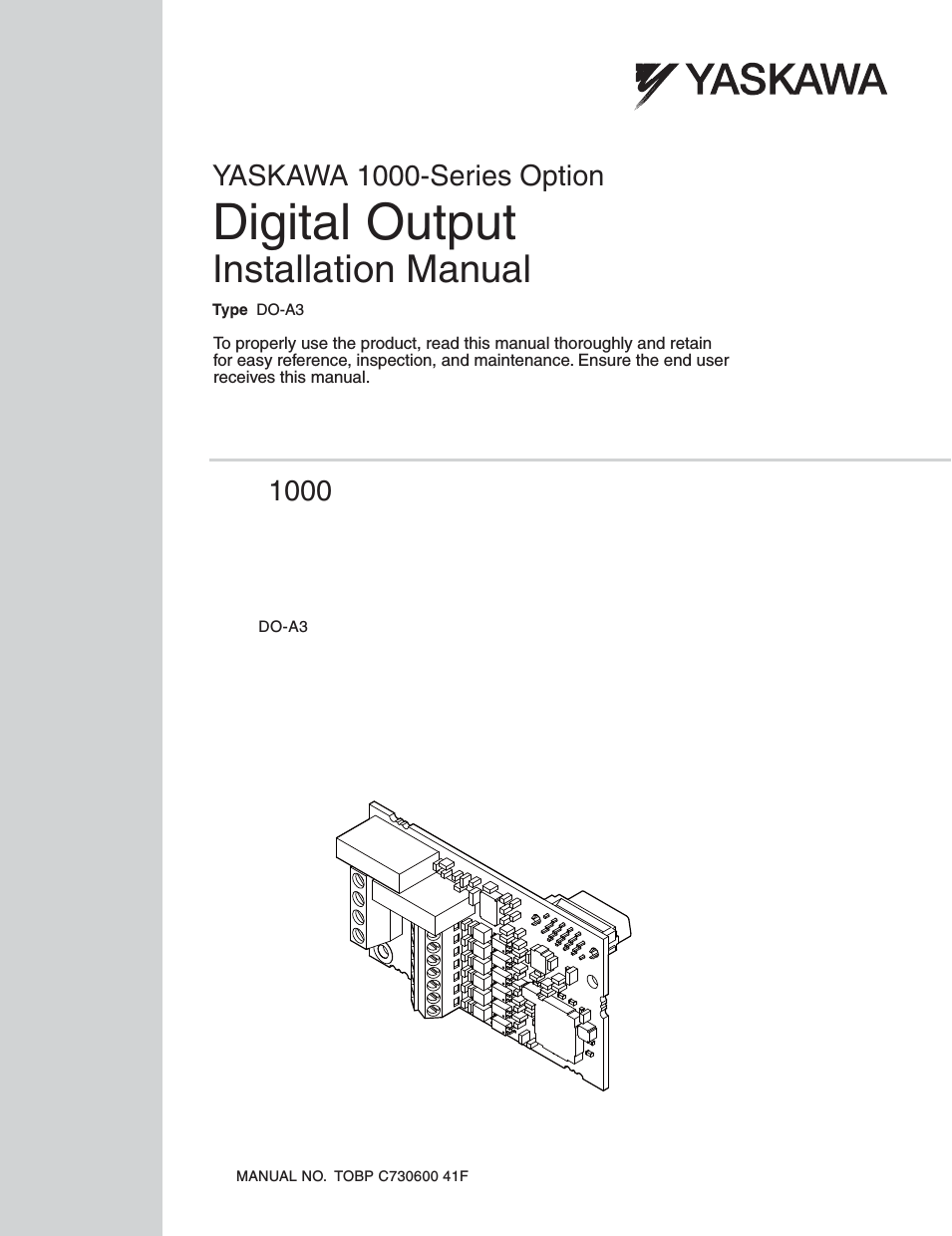


Table of contents
Document Outline
- C16_Service_Manual_Frontend_Finalized(TitlePage&CopyrightPage_Rev. 5.0).pdf
- Section 1: Specifications
- Regulatory Compliances
- Agency Listings
- Technical Specifications
- Visual Security Solutions (Specifications)
- VeriMarkTM Cards - 2-D holographic foil application
- Custom HoloMarkTM Cards
- Visual Security - Card Stock Part Numbers
- Visual Security - Fargo Certified Overlaminates (Special Order in 50 quantity minimum)
- Visual Security Card Stock - Tolerances
- VeriMarkTM - Application Specifications
- HoloMarkTM and Custom HoloMarkTM - Application Specifications
- Functional Specifications
- Printer Components: Top Cover to Parallel Interface Card
- Printer Components: Centronics-Type Parallel Interface
- Printer Components: Print Ribbons
- Printer Components: Resin-Only Print Ribbons
- Printer Components: Dye-Sublimation Print Ribbons
- Printer Components: Dye-Sublimation/Resin Print Ribbons
- Printer Components: Blank Cards
- Reviewing the upgraded 81754 PVC Cards
- Section 2: General Troubleshooting
- Safety Messages (review carefully)
- Communications Errors
- Card Feeding Errors
- Print Process Errors
- Card Jam Errors
- Ribbon Errors
- Encoding Errors
- Diagnosing Image Problems
- Resolving the Pixel Failure problems
- Resolving the Card Surface Debris problems
- Resolving the Incorrect Image Darkness problems
- Resolving the Ribbon Wrinkle problems
- Resolving the Excessive Resin Printing problems
- Resolving the Incomplete Resin Printing problems
- Resolving the Image Placement problems
- Resolving the Poor Image Quality problems
- Running the Self Test
- Interfacing Information
- Section 3: Printer Adjustments
- Safety Messages (review carefully)
- C16 Print Driver Options
- Using the Settings dialog box
- Using the Card tab
- Using the Device Options tab
- Using the Image Color tab
- Using the Calibrate tab
- Using the Magnetic Encoding tab
- Using the Magnetic Track Selection radio buttons
- Using the Magnetic Track Options radio buttons
- Using the Bit Density radio buttons
- Using the Character Size radio buttons
- Reviewing the Enable MLE Support checkbox
- Using the ASCII Offset radio buttons
- Using the LRC Generation radio buttons
- Using the Character Parity radio buttons
- Using the Verification radio buttons and Retries selection
- Using the Shift Data Left checkbox
- Reviewing the ISO Track Locations
- Sending the Track Information
- Entering the Track Information
- Reviewing Tracks 1, 2 and 3 (in table format)
- Reviewing the Track Data Note
- Reviewing the ASCII Code and Character Table
- Using the Overlay/Print Area tab
- Using the Overlay/Print Area dropdown menu
- Using the Overlay/Print Area
- Using the Defined Area Option
- Using Security Options (Visual Security Solutions)
- Selecting Orientation - Landscape under Card tab
- Selecting the Visual Security Solutions dropdown menu (A to D)
- Selecting Orientation - Portfolio under Card tab
- Selecting the Visual Security Solutions dropdown menu (E to H)
- Selecting the VeriMark radio button
- Selecting the HoloMark radio button
- Reviewing the Custom VeriMark Card (Custom Graphic in a 2D foil)
- Reviewing the Custom HoloMark Card (Custom Graphic in a 2D foil)
- Using the K Panel Resin tab
- Selecting from the Print All Black With K Panel options
- Selecting the Full Card option
- Selecting the Defined Area(s) option
- Selecting the Undefined Area(s) option
- Selecting the Defined Area(s) function
- Selecting the Defined Area(s) function (continued)
- Selecting the Defined Area(s) function (continued)
- Selecting the Defined Area(s) function (continued)
- Selecting the Defined Area(s) function (continued)
- Selecting the Defined Area(s) function (continued)
- Selecting the Defined Area(s) function (continued)
- Selecting the Defined Area(s) function (continued)
- Selecting the Print YMC under K and Print K Only options
- Section 4: Cleaning
- Section 5: Parts Replacement
- Safety Messages (review carefully)
- Reviewing the Printer Components
- Cover Removal
- Board, Interface and Printhead Replacements
- Motor and Mag Head Replacements
- Replacing the Headlift Motor Assembly (830143)
- Replacing the Card Feed Motor Assembly (830145)
- Replacing the Ribbon Drive Motor Assembly (830147)
- Replacing the Stepper Motor assembly (810113)
- Securing the current Stepper Motor Bracket and Fastener for increased belt tension
- Replacing the Magnetic Head Assembly (High-Coercivity: 810182 or Low- Coercivity: 810182)
- Sensor Replacement
- Replacing the Card Sensor Assembly (830135)
- Replacing the Upper Ribbon Sensor Assembly (83015111)
- Replacing the Encoder Wheel Sensor Assembly (830149)
- Replacing the Lid Sensor Assembly (810174)
- Replacing the Ribbon ID Sensor Board Assembly (820543)
- Replacing the Lower Ribbon Sensor Assembly — C16 (83012612)
- Roller Replacement
- C11/C16 Idler Spring Removal and Replacement Kit Instructions
- Technician Review - Idler Spring Replacement Kit for the C11 Card Printers without a Magnetic Encoder or for all C16 Card Printers
- Technician Review - Idler Spring Replacement Kit for the C11 Card Printers with the Magnetic Encoder
- Technician Review - Required Tools for both procedures
- Technician Review – Removal and Replacement Procedure No. 1
- Removing and replacing the Idler Springs on the C11 Card Printers without the Magnetic Encoder and for all C16 Card Printers
- Technician Review – Removal and Replacement Procedure No. 2
- Removing and replacing the Idler Springs on the C11 Card Printers with the Magnetic Encoder
- Technician Review – Photos related to Procedures No. 1 and No. 2
- Technician Review - Replacement parts for the C11 Card Printers without the Magnetic Encoder and for all C16 Card Printers
- Technician Review - Replacement parts for the C11 Card Printers with the Magnetic Encoder
- Section 6: Packing the Card Printer
- Section 7: Board Level Diagnostics
- Section 8: Firmware Upgrades
- Section 9: Fargo Technical Support
- Section 10: Reviewing the C16 Spare Parts List
- Glossary of Terms
- Glossary of Terms (continued)
- Glossary of Terms (continued)
- Glossary of Terms (continued)
- Glossary of Terms (continued)
- Glossary of Terms (continued)
- Glossary of Terms (continued)
- Glossary of Terms (continued)
- Glossary of Terms (continued)
- Glossary of Terms (continued)
- Glossary of Terms (continued)
- Glossary of Terms (continued)
- Glossary of Terms (continued)
- Glossary of Terms (continued)
- Glossary of Terms (continued)
- Glossary of Terms (continued)
- Glossary of Terms (continued)
- Glossary of Terms (continued)
- Glossary of Terms (continued)
- Glossary of Terms (continued)
- Index
- Appendix A: Engineering Drawings
- Appendix B: Technical Updates
- Appendix C: Miscellaneous
Related manuals for 1000 Series Drive Option - Digital Output Installation


New Manuals
- ZyXEL Communications ZyXEL G-162 Video Gaming Accessories User Manual
- ZyXEL Communications EW103U/A Video Gaming Accessories User Manual
- Western Telematic RSM-8 Video Gaming Accessories User Manual
- Western Telematic RSM-32DC Video Gaming Accessories User Manual
- Western Telematic RSM-32 Video Gaming Accessories User Manual
- Western Telematic RSM-16DC Video Gaming Accessories User Manual
- Western Telematic RSM-16 Video Gaming Accessories User Manual
- Viking Electronics FBI-1A Video Gaming Accessories User Manual
- Viking Electronics DVA-500A Video Gaming Accessories User Manual
- Viking Electronics DVA-3003 Video Gaming Accessories User Manual
- Viking Electronics DVA-2W Video Gaming Accessories User Manual
- Viking Electronics DVA- 1003B Video Gaming Accessories User Manual